PDP-5000EX
74
1234
1234
C
D
F
A
B
E
No
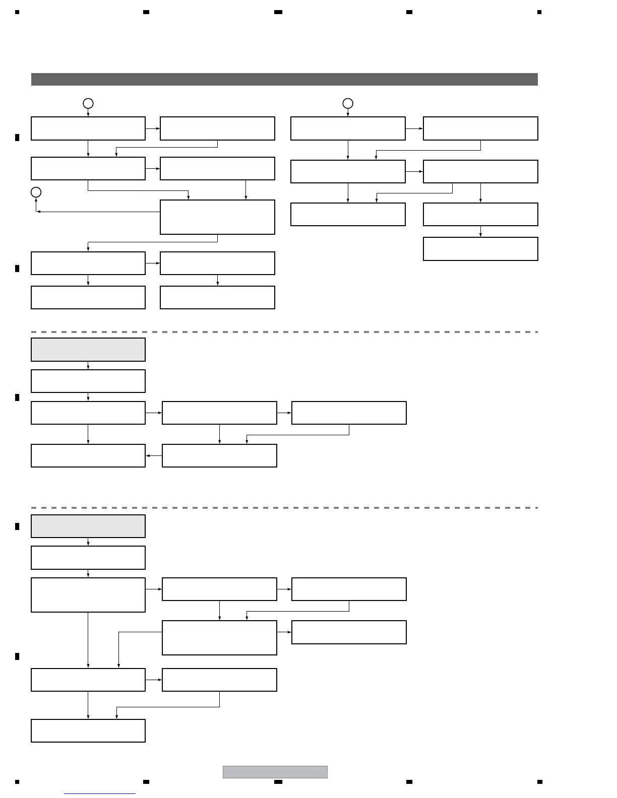
Is the waveform normal when the
voltage is applied to the panel?
(See the oscilloscope photos.)
Are all the connectors properly
connected?
Reconnect the connectors.
No
Set the VXNRST voltage correctly.
C
E
NG
Yes
Is the VXNRST set voltage
(-170 V) correctly set?
Yes
Another Assy may be in failure.
X DRIVE Assy
No
Replace the FFC cables.
Replace the DIGITAL Assy.
Replace the X DRIVE Assy.
NG
NG
Yes
Yes
Is the input signal normal?
(See the oscilloscope photos.)
No
Are all the connectors properly
connected?
Reconnect the connectors.
No
D
NG
Yes
Is the TCP control signal normal?
(See the oscilloscope photos.)
Yes
ADDRESS Assy
Replace the panel chassis.
Replace the DIGITAL Assy.
Yes No
NG
Replace the FFC cables.
Is the input signal normal?
(See the oscilloscope photos.)
No
Flowchart of Failure Analysis for The Drive Assy (2)
Is the TCP control signal normal?
No
NG
NG
Yes Yes
No
Are the FFC cables properly
connected?
Replace the DIGITAL Assy.
Properly connect the FFC cables.
The abnormality is associated with
one address or one TCP?
Diagnose the ADDRESS Assy.
In most cases of damage on one line,
the panel chassis must be replaced.
If the FFC cable that connects the DIGITAL and ADDRESS Assys is in failure,
the abnormality is associated with one address in most cases.
Replace the panel chassis.
No
NG
NG
Yes
Yes
Yes
No
Is the cable connected properly
to the 15-pin connector?
Is the cable connected properly
to the 90-pin connector?
Connect the cable properly.
No
Connect the cable properly.
Yes
Is the waveform of the SCAN IC
control signal from the Y DRIVE
Assy normal?
Is the waveform normal when the
voltage is applied to the panel?
(See the oscilloscope photos.)
No
Replace the Y DRIVE Assy.
The abnormality is associated
with a single scan line.
Diagnose the SCAN Assy.
Care must be taken that no dirt or dust is attached or gets in.
(The SCAN IC may be damaged.)
Replace the SCAN Assy.
Failure analysis for the
drive system ⇒ DR3
Failure analysis for the
drive system ⇒ DR4

 Loading...