4.19
ELECTRONIC FUEL INJECTION
4
Checking TPS Reading
1. Remove the lower seat base to access the sensor connector.
2. Assemble the TPS Tester according to the instructions.
Refer to “TPS Tester / Regulator” for proper set-up and
testing. Verify the 9 volt tester battery is new.
3. Disconnect the vehicle chassis harness from the TPS.
4. Plug the TPS Tester harness into the TPS harness.
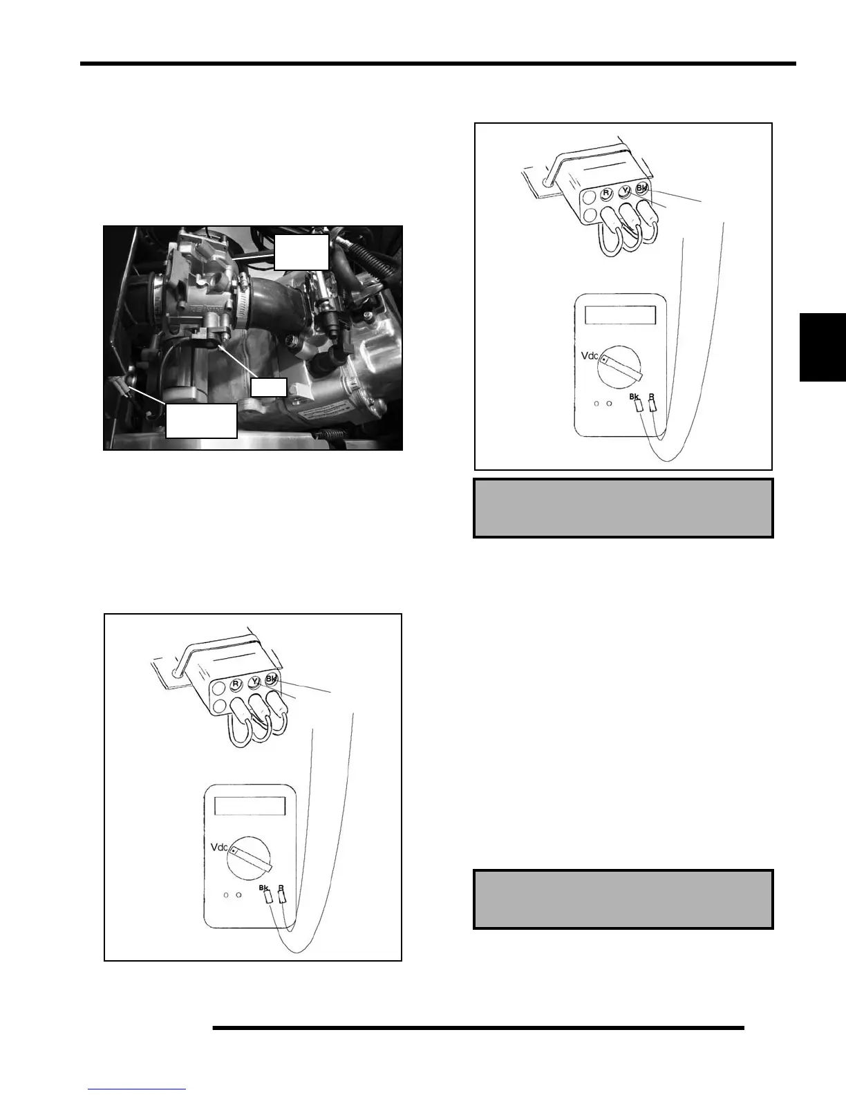
5. Set your voltmeter to read Vdc. Connect the red voltmeter
probe into the “Y” test port and the black voltmeter probe
into the “Bk” test port.
6. Move the throttle open and closed slowly while reading the
display. The voltage should increase and decrease
smoothly without any “jumps” when the throttle is applied.
7. If voltage varies with throttle movement, continue on to
Step 8. If the sensor did not function correctly, replace it.
8. Allow the throttle foot pedal to rest in the idle position. The
voltmeter should read .660 ± .010 volts.
9. If the voltage does not read within the specification,
proceed to the “TPS Adjustment” procedure. If the
voltage reading is within specification, no adjustment is
required.
TPS Adjustment
NOTE: This procedure should be performed after
you have checked the TPS reading. Refer to
“Checking TPS Reading” procedure before making
any adjustments.
1. Make sure the TPS Tester harness is still connected to the
TPS harness.
2. Loosen the mounting screw (B) holding the TPS to the
throttle body (see Figure 4-19).
3. Rotate the TPS until your voltmeter reads .660 ± .010 volts
(see Figure 4-18).
4. Retighten the mounting screw, and verify the voltage did
not change. If the voltage changed, repeat steps 2 - 4.
5. Reconnect the TPS harness to the vehicle harness.
TPS
Connector
TPS
Throttle
Body
No “Jumps”
0.66 ~ 3.7
Black
Red
Pink
Black
Probe
Red
Probe
in read out
PU-47082 Tester
TPS Output Reading
.660 ± .010 Vdc
TPS Output Reading
.660 ± .010 Vdc
Should Read
.660
Black
Red
Pink
Black
Probe
Red
Probe
.660 ± .010 Vdc
PU-47082 Tester
Figure 4-18
 Loading...