7.28
FINAL DRIVE
Installation
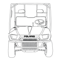
1. Apply Anti-Seize compound onto the mid gearcase output
shaft splines. Slide mid drive shaft (A) onto the mid
gearcase output shaft (B).
2. Install the outer end of the mid drive shaft into the hub
carrier (C).
3. Lift hub carrier into place and install bolt to upper control
arm. Torque bolt to 35 ft. lbs. (47 Nm).
4. Pull drive shaft outward and install hub onto drive shaft
splines. Apply Anti-Seize compound to the axle splines.
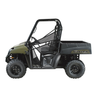
5. Install the flat washer (A) and cone washer (B) with domed
side facing outward. (Refer to next photo)
6. Install the castle nut (C), wheel, and wheel nuts.
7. Remove jackstand and torque mid hub nut to 110 ft. lbs.
(149 Nm) and wheel nuts to 35 ft. lbs. (47 Nm).
8. Install a new cotter pin. Tighten nut slightly to align holes
if required.
9. Install hub cap.
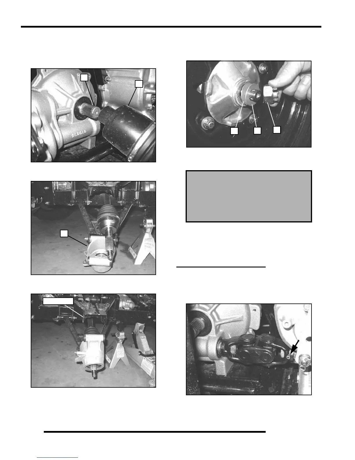
MID PROPSHAFT (6X6)
Removal
1. Use the Roll Pin Removal Tool (PN 2872608), to remove
the roll pin from prop shaft at rear of transmission.
2. The transmission or middle differential mounting will have
to be loosened to allow the propshaft to slide off of the
transmission output shaft.
A
B
C
Upper Bolt
Mid Hub Nut Torque:
110 ft. lbs. (149 Nm)
Mid Wheel Nut Torque
35 ft. lbs. (47 Nm)
A
B
C
 Loading...