8.2
TRANSMISSION
TORQUE SPECIFICATIONS
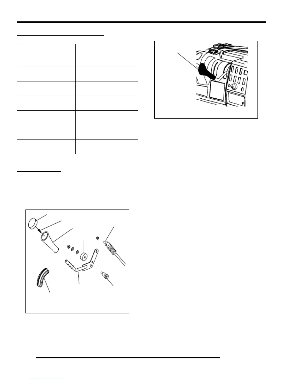
SHIFT LEVER
Removal
1. Disconnect linkage cable from shifter.
2. Remove one bolt attaching the gear shift selector mount to
machine frame.
3. Remove the shift lever cover and then remove the screw.
Pull off the shifter knob.
4. Lift the gear shift selector out of mounting bracket and
away from frame.
Installation
1. Repeat the steps in reverse order to install the gear shift
selector.
SHIFT LINKAGE
Inspection
Linkage rod adjustment is necessary when symptoms include:
• No All Wheel Drive light
• Noise on deceleration
• Inability to engage a gear
• Excessive gear clash (noise)
• Shift selectors moving out of desired range
NOTE: Remove necessary components to gain
access to shift linkage cable ends (i.e. exhaust heat
shield, exhaust pipe, etc.).
1. Inspect shift linkage cable, clevis pins, and pivot bushings
and replace if worn or damaged.
2. Be sure idle speed is adjusted properly.
ITEM TORQUE VALUE
Transmission Fill Plug
10-14 ft. lbs.
(14-19 Nm)
Transmission Drain Plug
10-14 ft. lbs.
(14-19 Nm)
Transmission Case Bolts
27-34 ft. lbs.
(37-46 Nm)
Bell Crank Nut
12-18 ft. lbs.
(16-24 Nm)
Bell Crank Gear Cover
7-9 ft. lbs.
(10-12 Nm)
Transmission Mounting
Bolts
25 ft. lbs. (35 Nm)
Transmission
Lubricant / Amount
AGL Gearcase Lube
43.6 oz. (1290 ml)
Cover
Shifter knob
Bearing
Cable
Bolt
Shifter
Grommet
Screw
Shift Lever Breakdown
Shift Lever Location
Shift Lever
 Loading...