5.22
BODY / STEERING / SUSPENSION
SWING ARM (6X6)
Removal
1. Support machine on a level surface.
2. Remove rear wheels.
NOTE: The rear axle may be removed to ease the
removal of the swing arm. Refer to Chapter 7, “REAR
AXLE HOUSING REMOVAL/INSPECTION”.
3. Support swing arm, remove rear axle shocks.
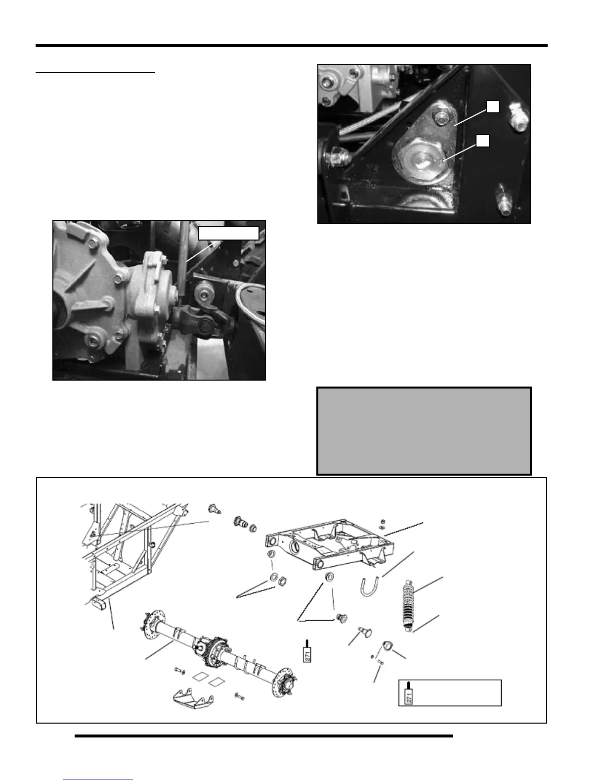
4. Drive spring pin out of rear propshaft at middle angle drive
using the Roll Pin Removal Tool (PN 2872608).
NOTE: Use jacks and jackstands to help remove the
swing arm assembly.
5. Remove the pivot bolt lock brackets (A), swing arm pivot
bolts (B), bolts swing arm bushings, lower swing arm and
rear axle.
Installation
1. Raise swing arm assembly and align the drive shaft to
the rear gearcase splined shaft (lube splines).
2. Insert new bushings, check pivot bolts for wear, replace if
necessary, torque bolts to 150 ft. lbs (75.9 Nm). Install
bolt lock brackets and bolts, torque to 30 ft. lbs. (41 Nm).
3. Install rear coil over shocks onto swing arm, torque bolts
to 30 ft. lbs (41 Nm).
4. Install rear wheels, lower machine.
5. Insert new spring pin on rear propshaft.
PN 2872608
Pivot Bolt and Nut Torque:
150 ft. lbs. (75.9 Nm)
Rear Shock Mount Bolt Torque:
30 ft. lbs. (41 Nm)
A
B
Frame
Rear Axle
Washer & Bolt
Bushings
Swing arm
U-Bolt
Shock Coil
30 ft. lbs.
(41 Nm)
Bolt Lock
Bracket
Pivot Bolt
150 ft. lbs.
(203 Nm)
30 ft. lbs.
(41 Nm)
Apply Loctite
TM
271
 Loading...