10.16
ELECTRICAL
ALL WHEEL DRIVE (AWD) COIL
Operation Overview
• When the AWD switch is “ON”, 12 VDC power is
present at the hub coil.
• If the criteria is met, the instrument cluster provides a
ground path at pin #16 (Brown/White wire). When this
occurs the AWD icon should display in the instrument
cluster.
• The AWD system must be grounded to operate.
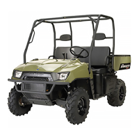
Diagnosing System Failures
• Verify the AWD switch is functional and that a
minimum of 11 volts is present at the hub coil.
• Verify the AWD hub coil is functional. Test the AWD
hub coil using an ohm meter. See specifications below:
• Verify the wiring harness, wiring, connectors,
connector pins and grounds are undamaged, clean and
connected properly.
• Verify continuity of wire connections with a volt/ohm
meter.
IMPORTANT: Verify all wires and wiring connections
have been tested properly with a known good volt/
ohm meter before suspecting a component failure.
80% of all electrical issues are caused by bad/failed
connections and grounds.
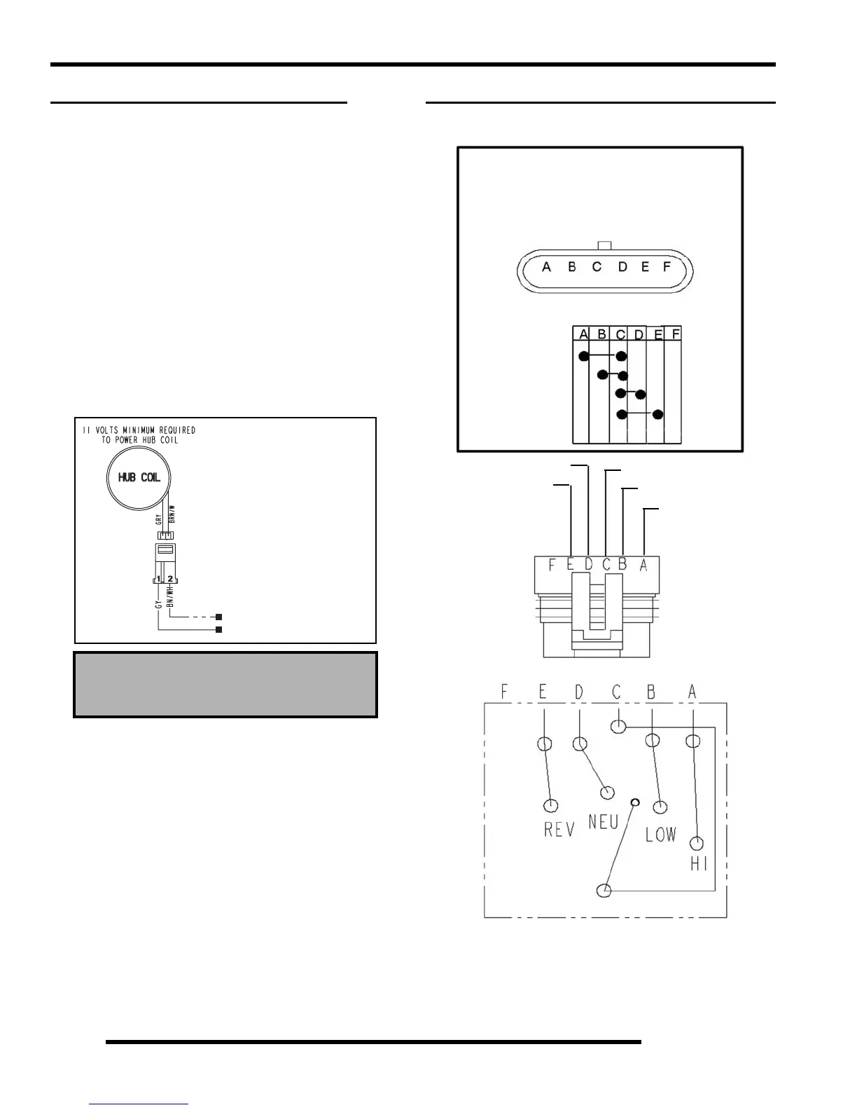
GEAR POSITION INDICATOR SWITCH
Test Diagram
AWD Hub Coil Resistance:
24
± 5%
7HVW5HVLVWDQFH
5HDGLQJVVKRXOGEH
*<WR%1:+a2KPV
*<WR*URXQG1R&RQQHFWLRQ
NOTE: Also see “INSTRUMENT CLUSTER
TROUBLESHOOTING” for switch circuit.
TRANSMISSION SWITCH
High / Low / Neutral / Reverse Switch
High Range
Low Range
Neutral
Reverse
Violet
Green/White
Brown/Red
White/Blue
Blue/Red

 Loading...