7.38
9929422 R02 - 2017-2019 ACE 900 Service Manual
© Copyright Polaris Industries Inc.
11. Attach shock to A-arm with fastener. Torque lower
shock bolt to specification.
TORQUE
Shock Mounting Fastener:
42 ft-lbs (57 Nm)
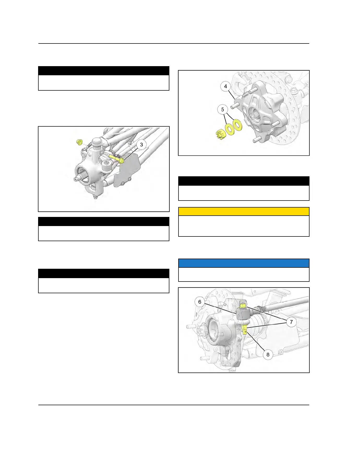
12.Install the upper joint end into the front bearing
carrier.
13.Install a new upper ball joint pinch bolt
e
and nut.
Torque to specification.
TORQUE
Ball Joint Pinch Bolts:
42 ft-lbs (57 Nm)
14.Install the fastener retaining the front stabilizer bar
link to the upper control arm. Torque fastener to
specification.
TORQUE
Stabilizer Link Fasteners:
42 ft-lbs (57 Nm)
15.Apply Anti-Seize to drive shaft axle splines.
16.Install front wheel hub assembly
r
, cone washers
t
,
and hand tighten the castle nut. Install washers with
domed side out.
17.Install new brake caliper mounting bolts and torque to
specification.
TORQUE
Front Caliper Mounting Bolts:
30 ft-lbs (54 Nm)
CAUTION
New bolts have a pre-applied locking agent which is
destroyed upon removal. Always use new brake caliper
mounting bolts upon assembly.
18.Install the steering tie rod end
y
onto the front
bearing carrier.
NOTE
Refer to the photo below to ensure proper placement of
the tie rod end.
FINAL DRIVE
 Loading...