7.22
FINAL DRIVE
3. Install and torque lower control arm bolts.
4. Lift bearing carrier until top aligns with upper control arm.
Install and torque upper control arm bolt and torque to
specification.
5. Pull drive shaft outward and install hub onto driveshaft
splines.
6. Install cone washers with domed side facing outward.
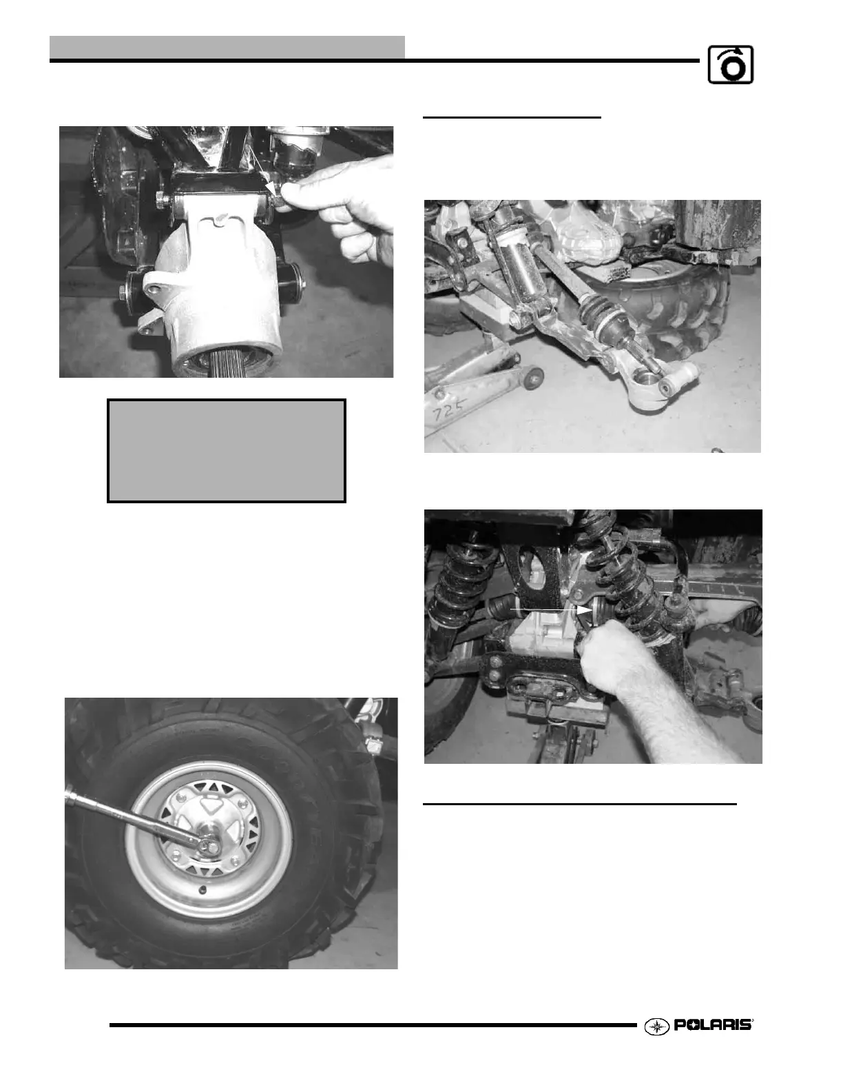
7. Install retainer nut, wheel and wheel nuts.
8. Remove jackstand and torque axle nut and wheel nuts.
9. Install a new cotter pin. Tighten nut slightly to align holes
if required.
10. Install hub cap.
REAR CV SHAFT
Removal
1. Remove rear hub; see “REAR HUB REMOVAL”.
2. Tip hub outward and remove shaft from hub.
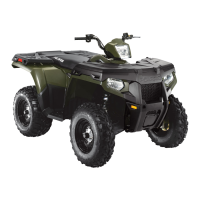
3. Pry and pull sharply outward to remove shaft from
transmission. Install a new lock ring upon assembly.
DRIVE SHAFT AND CV JOINT
HANDLING TIPS
Care should be exercised during driveshaft removal or when
servicing CV joints. Driveshaft components are precision
parts.
Cleanliness and following these instructions is very important
to ensure proper shaft function and a normal service life.
Lower Control Arm Bolt
Torque: 50 ft. lbs. (68 Nm)
Upper Control Arm Bolt
Torque: 35 ft. lbs. (48 Nm)
Pull outward sharply to
remove from transmission
 Loading...