9.11
ELECTRICAL
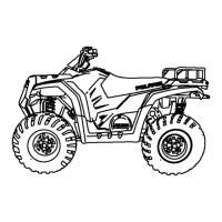
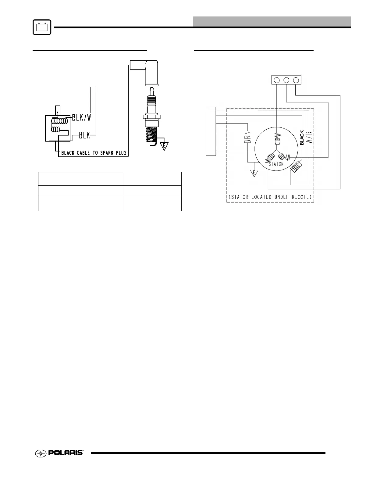
IGNITION COIL TESTING STATOR FUNCTION TEST
Three tests can be performed using a multimeter to determine
the condition of the stator.
TEST 1: Resistance Value of Each Stator Leg
1. Measure the resistance value of each of the three stator legs:
W1 to W2, W1 to W3, and W2 to W3. Each should measure
0.314ohms.
2. Measure each of the white wires to ground, the reading
should be (O.L.).
NOTE: Significant variations in resistance readings
between each circuit is an indication that one of the three
circuits may be weak or failed.
TEST 2: Stator Output.
1. Place the red lead on the tester in the 10A jack.
2. Turn the selector dial to the AC-AMPs position.
3. Start the engine and let it idle (1200 RPM).
4. Separately test each leg of the stator by connecting the
meter leads to the wires leading from the alternator (W1 to
W2, W1 to W3, W2 to W3). Alternator Current Output
Reading should be no less than 8 AMPS.
NOTE: Use an inductive amp meter to test stator
amperage for engine speeds over 1200 RPM.
Wire Description Resistance
Primary Coil (BLK/W to BLK) .21 Ohms
Secondary Coil (Black to High Tension lead
without cap.)
3.2KOhms
 Loading...