Design Guide for the Polycom SoundStructure C16, C12, C8, and SR12
9 - 26
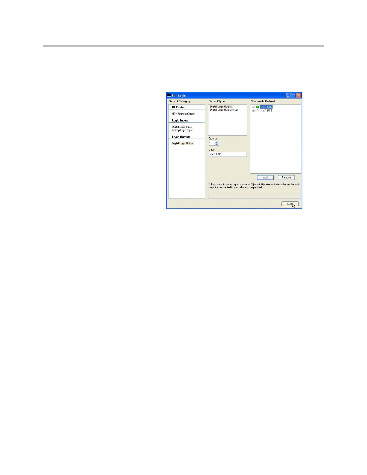
Step 1: Add a logic input and output pin for each microphone.
Use names for the logic pins that will make sense to you as you build your sys-
tem. If you have many microphones, you may add multiple digital logic
inputs and outputs by adjusting the quantity before clicking the add button.
Step 2: Create Mute Events on the button push
In this example it was desired to have the mute state toggled on all micro-
phones when the PTT button is pushed. To accomplish this we will create two
events – one to toggle the clink_mute parameter and one to use the clink_mute
parameter to mute “Mics”.
The first event “Toggle Clink Mute” will toggle the state of the clink_mute
parameter on SoundStructure device 1. If there are multiple SoundStructure
devices in the system, then additional events would be created to map
clink_mute on device 1 to clink_mute on device 2 and so on and finally map
the clink_mute on device N (N may vary from 2 to 8) back to the clink_mute
on device 1 to ensure the mute state is synced across multiple SoundStructure
devices.