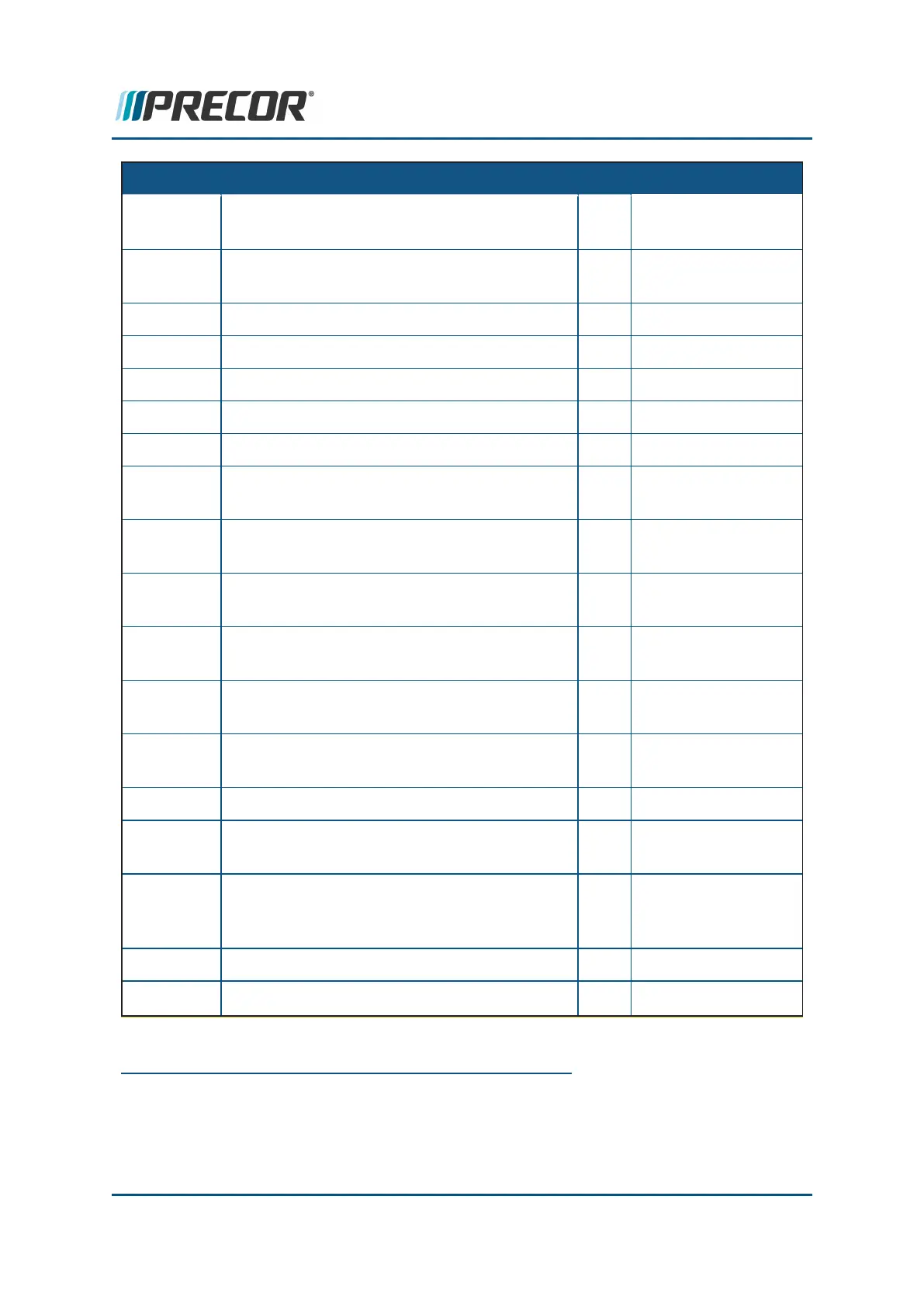
CONN
1
ID
NAME PIN Description
2 THERMAL
RESISTOR SENSE
MON
(2)
MONITOR (ASL
2
PCA
3
INTERFACE
CABLE)
1 +8 VDC
2 /BOOT_EN
3 TX
4 8V GND
5 D_RESET
6 RX
MTH DRIVE MOTOR THERMAL SWITCH 1 THERMAL SWITCH
SENSE
2 THERMAL SWITCH
SENSE
DBTH
(1)
DYNAMIC BRAKE RESISTER THERMAL
SWITCH
1 THERMAL SWITCH
SENSE
2 THERMAL SWITCH
SENSE
LIFT LIFT MOTOR PWR OUT & CONTROL 1 BLK -
POTENTIOMETER
2 RED -
POTENTIOMETER
3 NC
4 WHITE - MOTOR
COMMON
5 WHITE -
POTENTIOMETER
WIPER
6 NC
7 RED - MOTOR
1
connector
2
Active Status Light: Service and maintenance status light.
3
Printed circuit assembly, generally referred to as either an upper PCA or lower PCA.
Contact Precor Customer Support at support@precor.com or 800.786.8404 with
any questions.
Page 128
6 Replacement Procedures
Motor Controller (MC) Replacement
 Loading...