EasyManuals Logo

Quectel 5G Module Series Hardware Design

Quectel 5G Module Series
87 pages
To Next Page IconTo Next Page
To Previous Page IconTo Previous Page
Page #52 background imageLoading...
Page #52 background image
5G Module Series
RM500Q-AE&RM502Q-AE Hardware Design
RM500Q-AE&RM502Q-AE_Hardware_Design 51 / 86
The following table shows the RF status indicated by WWAN_LED#.
Table 23: Network Status Indications of WWAN_LED#
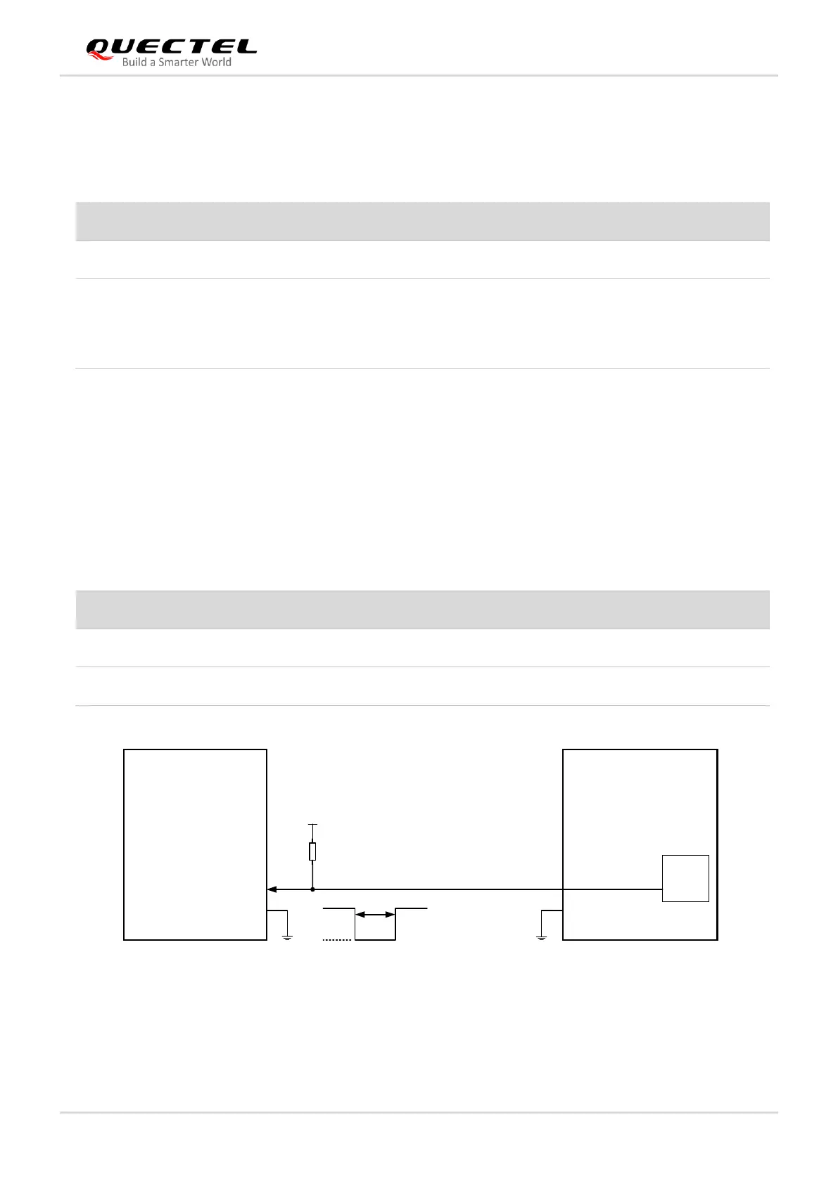
4.5.4. WAKE_ON_WAN#
The WAKE_ON_WAN# is an open drain pin, which requires a pull-up resistor on the host. When a URC
returns, a 1 s low level pulse signal will be outputted to wake up the host. The module operation status
indicated by WAKE_ON_WAN# is shown as below.
Table 24: State of the WAKE_ON_WAN#
Host Module
WAKE_ON_WAN#
BB
GPIO
23
VCC_IO_HOST
NOTE:
The voltage level on VCC_IO_HOST depends on the host side due to the open drain in pin 23.
Wake up the host
1s
H
L
R1
10k
Figure 26: WAKE_ON_WAN# Signal Reference Circuit
WWAN_LED# Level
Description
Low Level (LED ON)
RF function is turned on
High Level (LED OFF)
RF function is turned off if any of the following occurs:
The (U)SIM card is not powered.
W_DISABLE1# is at low level (airplane mode enabled).
AT+CFUN=4 (RF function disabled).
WAKE_ON_WAN# State
Module Operation Status
Output a 1 s low level pulse signal
Data is incoming (to wake up the host)
Always at high level
Idle/Sleep

Table of Contents

Other manuals for Quectel 5G Module Series

Questions and Answers:

Question and Answer IconNeed help?

Do you have a question about the Quectel 5G Module Series and is the answer not in the manual?

Quectel 5G Module Series Specifications

General IconGeneral
BrandQuectel
Model5G Module Series
CategoryMotherboard
LanguageEnglish

Related product manuals