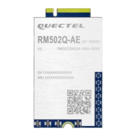
5G Module Series
RM500Q-AE&RM502Q-AE Hardware Design
RM500Q-AE&RM502Q-AE_Hardware_Design 5 / 86
Contents
Safety Information ....................................................................................................................................... 3
About the Document ................................................................................................................................... 4
Contents ....................................................................................................................................................... 5
Table Index ................................................................................................................................................... 8
Figure Index ............................................................................................................................................... 10
1 Introduction ........................................................................................................................................ 12
1.1. Introduction ............................................................................................................................... 12
1.2. Reference Standard .................................................................................................................. 12
1.3. Special Mark ............................................................................................................................. 13
2 Product Concept ................................................................................................................................ 14
2.1. General Description .................................................................................................................. 14
2.2. Key Features ............................................................................................................................. 15
2.3. Evaluation Board ....................................................................................................................... 18
2.4. Functional Diagram ................................................................................................................... 18
2.5. Pin Assignment ......................................................................................................................... 19
2.6. Pin Description .......................................................................................................................... 20
3 Operating Characteristics ................................................................................................................. 25
3.1. Operating Modes ....................................................................................................................... 25
3.1.1. Sleep Mode .................................................................................................................... 25
3.1.2. Airplane Mode ................................................................................................................ 27
3.2. Communication Interface with a Host ....................................................................................... 27
3.3. Power Supply ............................................................................................................................ 28
3.3.1. Decrease Voltage Drop .................................................................................................. 28
3.3.2. Reference Design for Power Supply .............................................................................. 29
3.3.3. Monitor the Power Supply .............................................................................................. 30
3.4. Turn on ...................................................................................................................................... 30
3.5. Turn off ...................................................................................................................................... 32
3.5.1. Turn off the Module through FCPO# ............................................................................. 32
3.5.2. Turn off the Module through AT Command ................................................................... 33
3.6. Reset ......................................................................................................................................... 34
4 Application Interfaces ....................................................................................................................... 36
4.1. (U)SIM Interface ........................................................................................................................ 36
4.1.1. Pin definition of (U)SIM .................................................................................................. 36
4.1.2. (U)SIM Hot-plug ............................................................................................................. 37
4.1.3. Normally Closed (U)SIM Card Connector...................................................................... 38
4.1.4. Normally Open (U)SIM Card Connector ........................................................................ 38
4.1.5. (U)SIM Card Connector Without Hot-plug ..................................................................... 39
4.1.6. (U)SIM Design Notices................................................................................................... 40
4.2. USB Interface ............................................................................................................................ 40

 Loading...