Layout and function 2
8
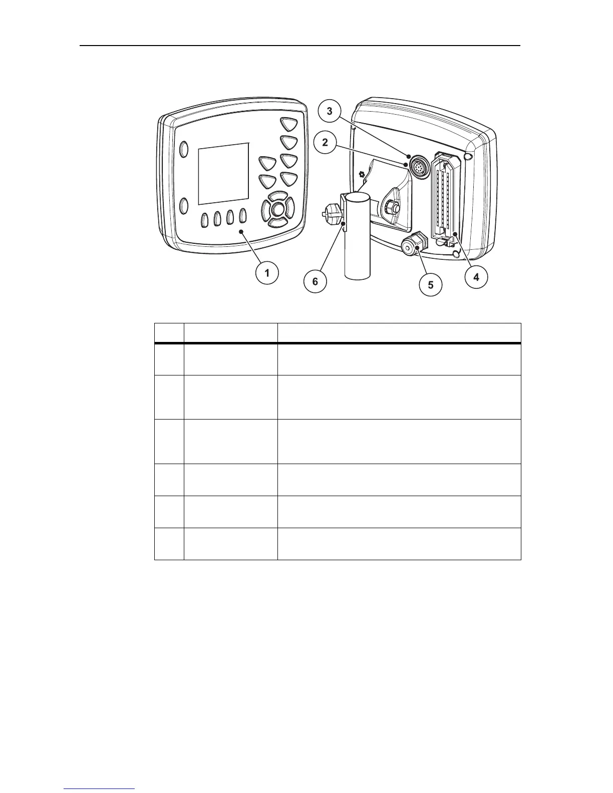
2.2 Layout of the control unit - Overview
Figure 2.1: Control unit Quantron E
No. Designation Function
1 Control panel Keys for operation of the unit and the display for ope-
rating screens.
2 V24 data port Serial interface (RS232) with LH 5000 and
ASD protocol, designed for connection of an RS232
Y- cable for connecting to a remote terminal.
3 8-pin plug connec-
tor
Plug connection (DIN 9684-1/ISO 11786) for con-
necting the 7-way to 8-way cable for the speed sen-
sor.
4 Machine cable plug
connector
39-pin plug connector for connecting the machine
cable to the positioning cylinder.
5 Power supply 3-pin plug connector conforming to DIN 9680 /
ISO 12369 for connecting the power supply.
6 Bracket Attachment for securing the control unit to the trac-
tor.