Attachment and installation 3
14
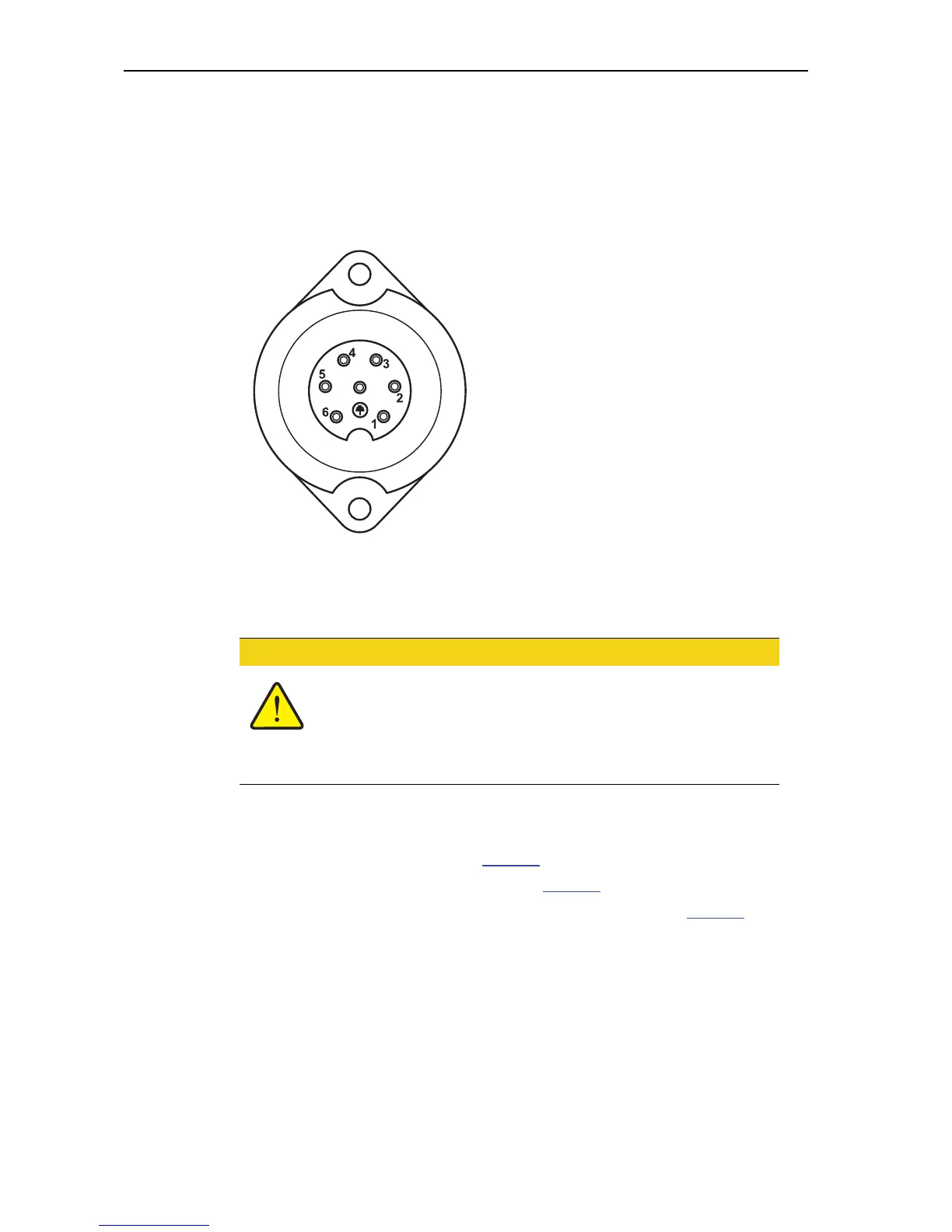
3.2.2 7-pin plug connector
The control unit receives the impulses for the current traverse speed via the 7-pin
socket (DIN 9684-1/ISO 11786. To do so, the 7-pin to 8-pin cable (accessory) is
connected to the ground speed sensor at the plug connector.
3.3 Connecting the control unit
Depending on the equipment, there are different methods of attaching the control
unit to the fertiliser spreader. For schematic terminal diagrams see below:
for the standard connection on page 16,
for the connection with wheel sensor onpage 17,
for the connection with wheel sensor and machine cable on page 18.
[1] PIN 1: Actual ground speed (radar)
[2] PIN 2: Theoretical ground speed (e. g.
gearbox, wheel sensor)
Figure 3.2: PIN assignment for 7-pin plug connector
n CAUTION
Note machine number
The control unit Quantron E is calibrated at the factory for the
fertiliser spreader with which it was delivered.
Connect the control unit control unit to the correct ferti-
liser spreader only.