Layout and function
11
2
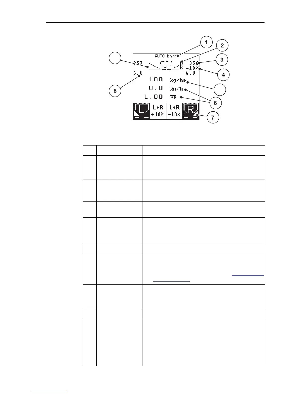
Figure 2.3:
Display on the control unit (using the operating screen as an example)
The icons and displays in the example have the following meaning:
No. Icon / Display Meaning (in the example)
1 Operating mode Shows the current operating mode.
Auto km/h uses the radar signal or wheel signal
for determining the speed.
2 Telimat icon This symbol appears if the Telimat Sensors are fit-
ted and the Telimat function is activated (factory
setting) or the T button has been activated.
3 Metering slide sca-
le opening right
Current opening position of the right hand metering
slide.
4 Weight change
right
Weight change (+/- ) in percent.
Display of quantity changes.
Range of values +/- 1..99 % possible.
5 Application rate Preset application rate.
6 Display fields Configurable display fields (here: ground speed, flow
factor).
Possible configuration: see section 4.8.2: Display
config., page 68.
7 Icon fields Icons assigned to fields depending on the menu.
Selection of the function by means of the
Function buttons located underneath.
8 Drop point Only AXIS 50.1 W: Display of the drop point position
9 Partial width right Display of status of partial width right.
No icon: partial width right not selected.
Empty icon (contour): Partial width right selec-
ted but not active.
Icon with black background: Partial width in
spreader operation.