Attachment and installation
17
3
Wheel sensor schematic terminal diagram:
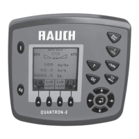
Figure 3.4: Schematic terminal diagram Quantron E (machine cable)
[1] RS232 serial interface
[2] 39-pin machine connector
[3] Battery
[4] Option (level sensor left/right)
[5] 3-pin plug connector as per DIN 9680 / ISO 12369
[6] 8-pin plug connector
[8] Ground speed sensor
[9] Option (Telimat sensor top/bottom)
[10] Weigh cell left/right (only on AXIS 30.1 W - 40.1 W - 50.1 W)
[11] Metering slide actuator left/right
[12] Option Y cable (V24 RS232 interface for storage medium)
[13] Option (GPS cable and receiver)
[14] Option drop point adjustment (only for AXIS 50.1 W)