CHAPTER 4
28 ISO Product Controller II and Hawkeye Operation Manual
The High and Low values will display the highest, average, and lowest active NCV duty cycles on the system. These
values will turn red if the values reach the maximum or minimum flow output capabilities of the NCV's for a given
spray tip size. The High value will be 100% or less due to the flow limitations of the selected spray tip. The Low
value may display the minimum nozzle PWM value, defaulted to 25%, or greater. When the operator is driving in a
straight line, the High, Average, and Low values should be within 1-2% of each other unless a flow offset is active
for any NCV. When Turn Compensation is utilized, the High and Low values will be significantly different, indicating
the outside NCV's are operating at a higher duty cycle than the inside NCV's. These values should correlate to the
NCV Duty Cycle values for the outermost active NCV's. The Average value is an average duty cycle of all active
NCV's. The system should be operated so that, when at optimal spray height, the average value is maintained near
70% duty cycle. This will ensure optimal straight line and turn compensated spray coverage.
NOTE: This setting will not display in Bypass or On/Off Nozzle Control mode if three or more injection
pumps are present or when the system is toggled in “Manual” application mode.
BOOM RECIRCULATION
NOTE: Turn on an output from the ECU that can open a valve to recirculate the product in the boom when
the active width is zero. The feature is only available on systems with less than 13 physical section
valves and cannot be used if injection is on the system.
WIRELESS CONTROL MODE
SECTION
The remote wireless diagnostic device will command the associated NCV’s on/off. The device will command the
boom valve and it’s associated NCV’s on/off.
NOZZLE
The remote wireless diagnostic device will command the individual NCV’s on/off if the remote device supports this
mode. The mobile application does not support this mode. This may require additional supporting software.
GROUP END NOZZLES
Enabling this setting will link the three nozzles at the end of the boom to the NCV directly beside them. When one
of the NCV’s are turned on, all linked nozzles will turn on.
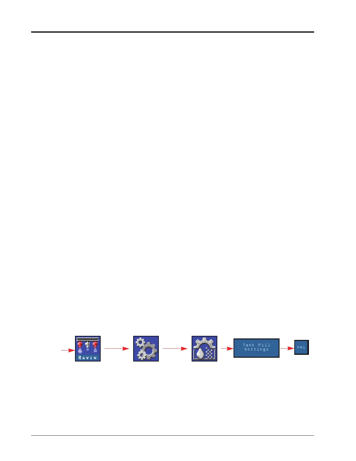
SYSTEM SETTINGS TAB - TANK FILL
To access the Tank Fill Settings menu for an injection product or the main Hawkeye product:
1. Open the UT Menu and select the Hawkeye
®
Menu button.
2. From the home screen, select the Tools Menu softkey along the right side of the display.
3. Select the System Settings tab along the top of the display.
Hawkeye Menu
Tools Menu
System
Settings
Tank Fill
Settings
UT Menu
Tank Fill
Settings
Select
Product
 Loading...