APPENDIX A
78 ISO Product Controller II and Hawkeye Operation Manual
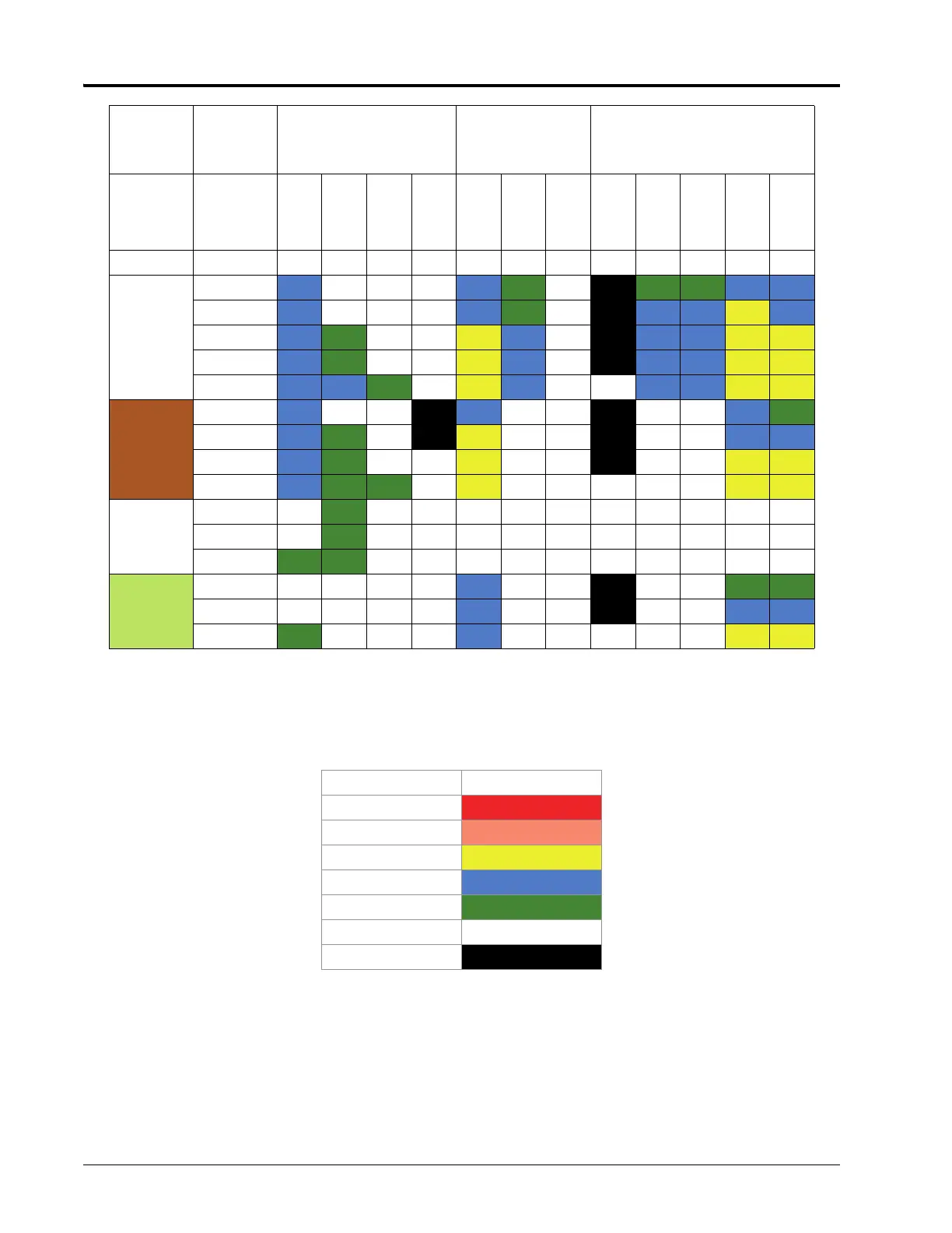
DRIFT CONTROL TABLE KEY
Refer to this key while using the drift control table:
TABLE 2. Number Key
APPLICATION SPEED GUIDE
The ranges for speed and flow rate provided in this section are for reference purposes only. Observed ranges may
vary depending upon application system plumbing and hardware. It is recommended to avoid operating at, or
close to, the upper and lower limits of the speed or flow rate ranges shown for each spray tip. The values in the
table below are based on 20” nozzle spacing.
08
20
C---C VC - UC VC VC C C
30
C XCXCXCC VC - UC C C M C
40
C VC XC XC M C- UC C C M M
50 C VC XC XC M C- UC C C M M
60
C C VC XC M C- XC C C M M
10
30
CXCXCUC C- - UC - - C VC
40
C VC XC UC M- - UC - - C C
50
C VC XC XC M- - UC - - M M
60
C VC VC XC M- - XC - - M M
12.5
40 VC
VC XC XC - - - - - - - -
50 C
VC XC XC - - - - - - - -
60
C VC XC XC - - - - - - - -
15
40 VC XC XC XC
C- - UC - - VC VC
50 C XCXCXC
C- - UC - - C C
60
C XCXCXCC- - XC - - M M
Drift Category Symbol and Color
Very Fine
VF
Fine
F
Medium
M
Coarse
C
Very Coarse
VC
Extremely Coarse XC
Ultra Course
UC
Tip Size
Boom
Pressure
(PSI)
Wilger
(www.wilger.net)
TeeJet
(www.teejet.co
m)
Hypro
(www.hypropumps.com)
Orifice
Size
PSI
ER
SR
MR
DR
XR/XRC
TT/2XTT
TTJ60
HF
GRD
LD
VP
TR
Gauge 110 110 110 110 110 110 110 110 110 110 110 120
 Loading...