Troubleshooting: Diagnostic Trouble Code (DTC) List 61
TROUBLESHOOTING
8. Use a small jumper wire (e.g. paper clip) to short the ground and signal sockets with a “short-no short” motion.
Each time the short is made, the total volume value should change by increments of one or more.
9. If the total volume does not increase, disconnect this section of flow meter extension cable and repeat this test
at the next connector closest to Product Controller II ECU. Replace defective cable as required.
10. If all cables test good, replace the flow meter.
11. After testing is complete, re-enter correct meter cal value and units.
DIAGNOSTIC TROUBLE CODE (DTC) LIST
The following trouble codes may be displayed by the Hawkeye
®
nozzle control system and should help the
operator to identify and correct issues with system during field operations:.
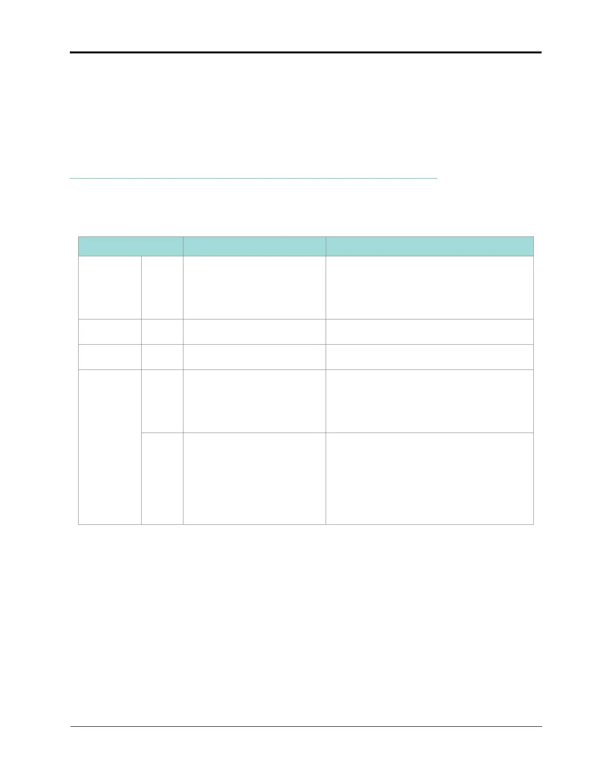
Code ID Description Recommended Actions
10 .13 UT display is not on-line
1. If this error occurs frequently, check the
ISOBUS connections and review the UT
display troubleshooting procedures.
2. Connect the Raven Service Tool to the
ISOBUS and verify communication.
158 .1 Logic SW power error
1. Verify logic voltage is at or above 4.8v to
Product Controller II ECU.
168 .1 Battery voltage error
1. Verify HC voltage to Product Controller II ECU
is above 9v.
630
.13 System calibration required
1. Complete the calibration wizard to configure
all required Hawkeye
®
system settings. Refer
to Chapter 3, System Calibration for
additional assistance with the calibration
wizard.
.31 Nozzle Calibration Error
1. Complete the calibration wizard to configure
all required Hawkeye
®
system settings. Refer
to Chapter 3, System Calibration for
additional assistance with the calibration
wizard.
2. Cycle system power.
3. Reset defaults.
 Loading...