If the operation method is improper, it will cause irreversible and serious damage to the
output optical cable during use.
After ensuring the cleanliness, install the B- type end cap. During the installation process, there
will be resistance when screwed to the bottom, which is a normal phenomenon. It is necessary
to ensure that there is no gap between the end cap and the main body sleeve. And then check the
finish and cleanliness of the end cap's glossy surface, as 错误!未找到引用源。9 shown.
Then connect the fiber optic cable output head to the cutting head (or welding head) with the B-
type end cap installed. This operation needs to ensure the cleanliness of the inner and outer
surfaces of the cutting head (or welding head) connector.
Note: The connection with the cutting head (or welding head) still needs to be carried out
in a clean workbench, and it is necessary to check the cleanliness and smoothness of the
relevant components of the cutting head (or welding head) itself.
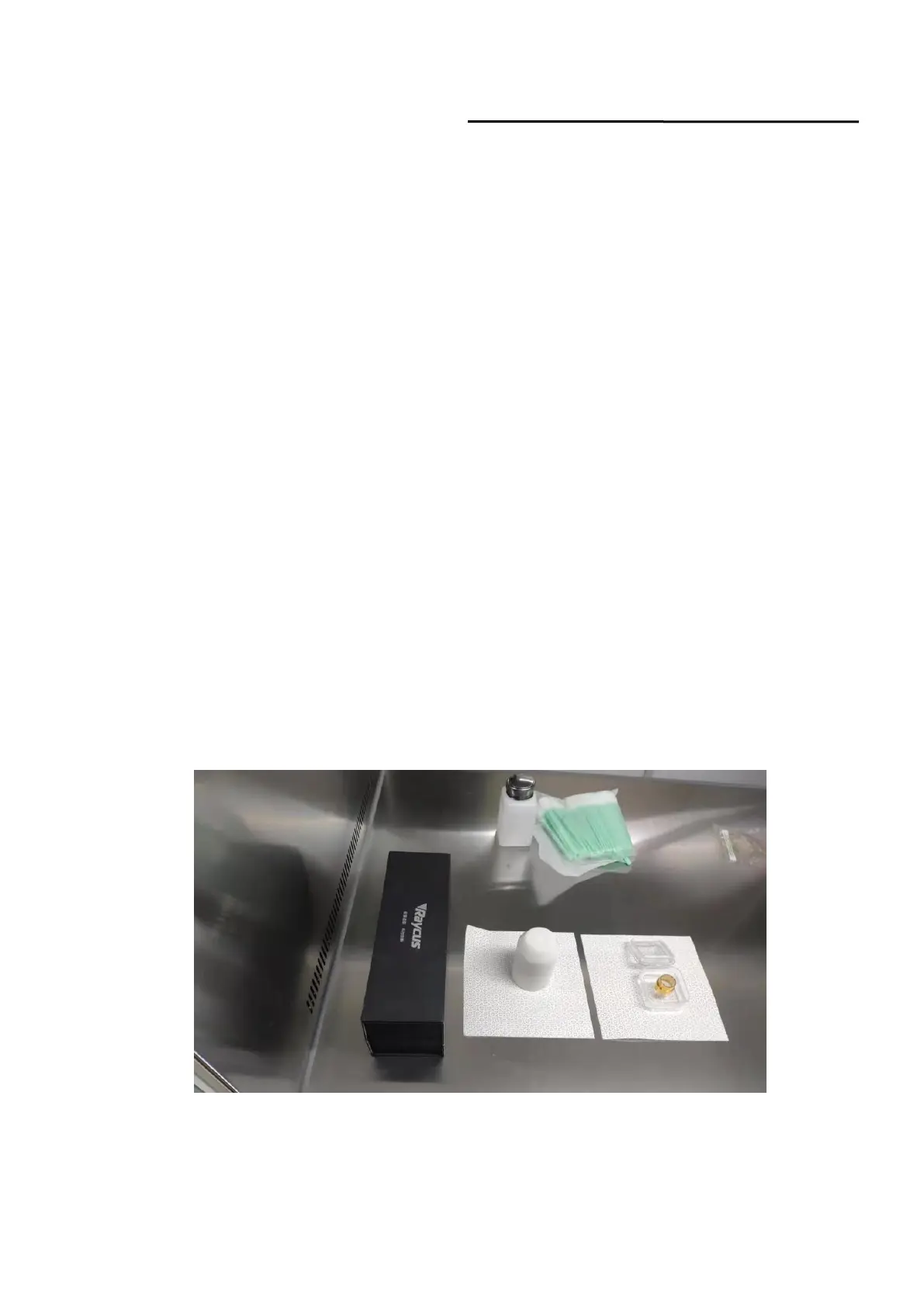
Keep the corresponding accessories as Figure 10 shown in order to facilitate the re-transportat-
ion of the laser or output cable.
Note: The fiber optic cable must be loaded with Type A end caps each time it is
transported. That is, every time the output optical cable is unloaded from the cutting head
and needs to be transported, the end cap of type B must be replaced with the end cap of
type A , and the white dust cover must be covered, and finally put into a black box for
transport.
Figure 10 Accessories that customers need to keep: black protective box,
white dust cover, type A end cover
 Loading...