TESTING the system
After validating and uploading the project to the MZERO and connecting all the safety
devices, you must test the system to verify its correct operation.
• This is done by forcing a change of status for each safety device connected to the MZERO
to check that the status of the outputs actually changes.
• The following example is helpful for understanding the TEST procedure.
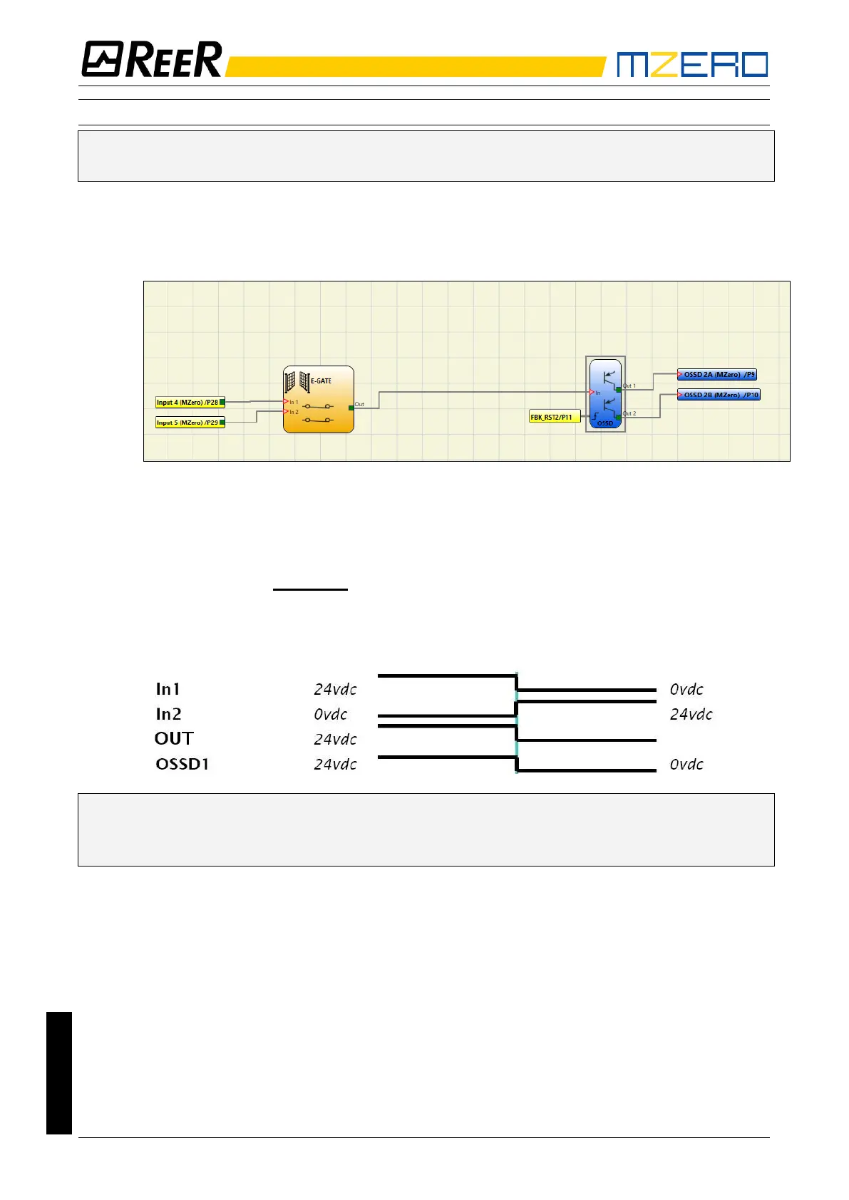
Figure 30
(t1) In the normal operating condition (E-GATE closed) Input1 is closed, Input2 is open and the
output of the E-GATE block is set to high logic level; in this mode the safety outputs
(OSSD1/2) are active and the power supply to the relative terminals is 24VDC.
(t2) When the E-GATE is physically opened, the condition of the inputs and thus of the outputs
of the E-GATE block will change: (OUT= 0VDC--->24VDC); the condition of the
OSSD1-OSSD2 safety outputs will change from 24VDC to 0VDC. If this change is
detected the mobile E-GATE is connected correctly.
For the correct installation of each external sensor/component refer to their installation
manual.
This test must be performed for each safety component in the project.