To enable this control, the test output signals must be configured (amongst those available). Test
signals are mandatory.
Test at start-up: If selected this enables the test at start-up of the external component. This test
is performed by pressing and releasing the safety mat to run a complete function test and enable
the output. This test is only requested at machine start-up (when the unit is switched on).
Filter (ms): This is used to filter the signals coming from the external contacts. The filter can be
configured to between 3 and 250 ms and eliminates any bouncing on the contacts. The length of
the filter affects the calculation of the unit's total response time.
Enable Error Out: If selected reports a fault detected by the function block.
Item description: This allows a description of the component's function to be entered. The text is
displayed in the top part of the symbol.
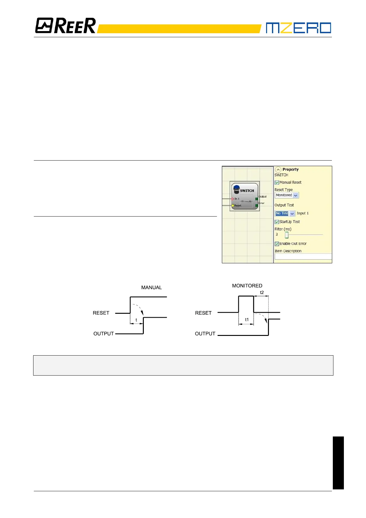
SWITCH
SWITCH function block verifies the input status of a
pushbutton or switch (NOT SAFETY SWITCHES). If the
pushbutton is pressed the output is 1 (TRUE). Otherwise,
the output is 0 (FALSE).
Parameters
Manual reset: If selected this enables the request to reset
each time the device is activated. Otherwise, enabling of the
output directly follows the input conditions.
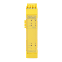
There are two types of reset: Manual and Monitored. When
Manual is selected the system only verifies the signal's
transition from 0 to 1.
If Monitored is selected the double transition from 0 to 1 and then back to 0 is verified.
➔ If the Manual Reset is active, a consecutive Input have to be used. Example: Input 1 is used
for the functional block, then Input 2 have to be used for the Reset Input.
Output test: This is used to select which test output signals are to be sent to the switch.
This additional control permits detection and management of any short-circuits between the lines.
To enable this control, the test output signals must be configured (amongst those available).
Test at start-up: If selected this enables the test at start-up of the switch. This test is performed by
opening and closing the switch contact to run a complete function test and enable the output. This
test is only requested at machine start-up (when the unit is switched on).
Filter (ms): This is used to filter the signals coming from the switch. The filter can be configured to
between 3 and 250ms and eliminates any bouncing on the contacts. The length of the filter affects
the calculation of the unit's total response time.
Enable Error Out: If selected reports a fault detected by the function block.
Item description: This allows a description of the component's function to be entered. The text is
displayed in the top part of the symbol.