Creating the diagram
Once you have selected your system composition, you are ready to configure the project.
The logic diagram is created using a DRAG&DROP function:
• Select the objects as required from the windows described previously (each single object is
described in detail in the following sections) and drag it into the design area.
• Now when you select the object the PROPERTIES window is enabled, where you must fill in
the fields as required.
• When you need to set a specific numerical value with a slide (eg filter) use the left and right
arrows on your keyboard or click the sides of the slider.
• Connect the objects by moving the mouse over the required pin and then dragging it onto the
pin to be connected.
• If the scheme requires the PAN function (moving working area in the window), select the object
to move and use the arrow keys on your keyboard.
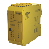
• If the scheme is very complicated and requires a connection between two elements very far,
use the “Interpage” component. The element “Interpage out” must have a name which, invoked
by the corresponding “Interpage in”, allows the desired link.
• When you need to duplicate an object, select it and press CTRL+C / CTRL+V keys on your
keyboard or click at the right mouse button and select context menu “Copy” and then “Paste”.
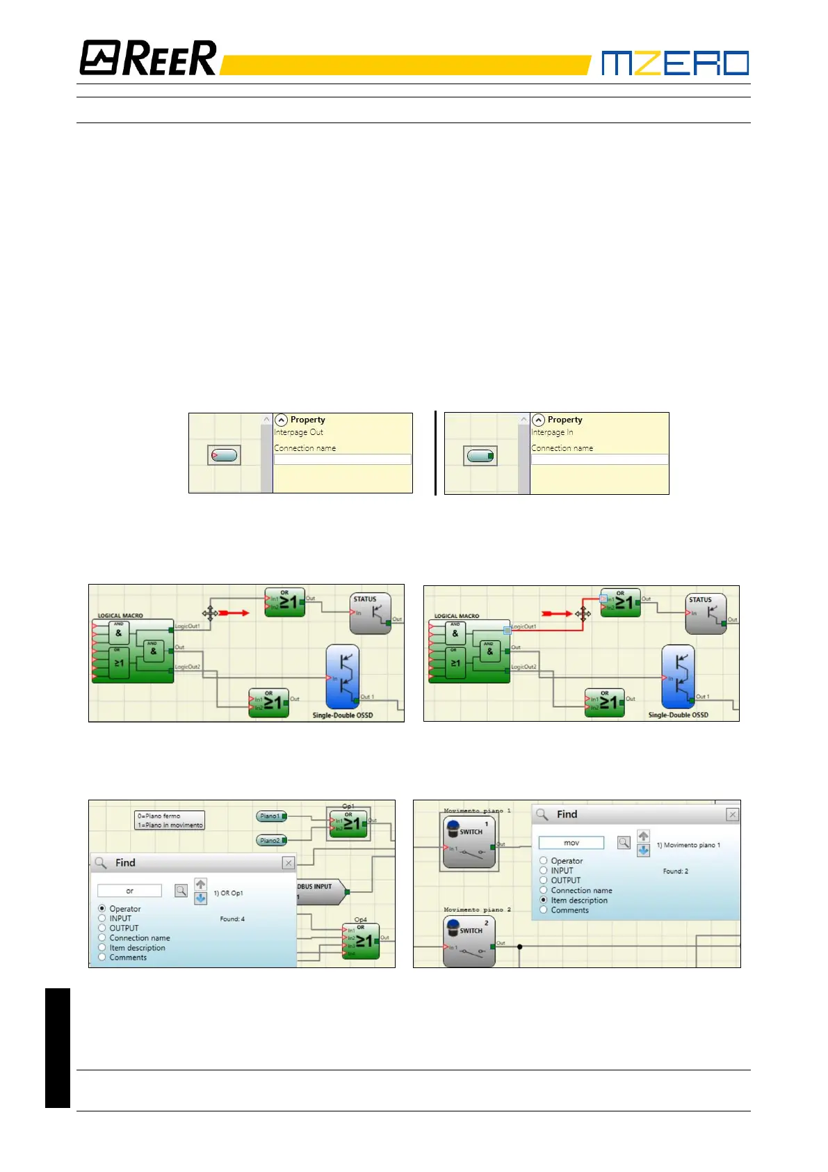
• Wires position: it is possible to move the wires for a better graphic visibility of the scheme. To
activate the function, simply place the mouse pointer and left click on the wire to be moved.
• When you need to delete an object or a link, select it and press DEL key on your keyboard.
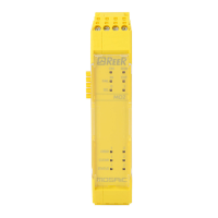
• Find function: (press CTRL + F) allows you to make search within the scheme based on a search
parameter. Research does not distinguish among upper and lower case.