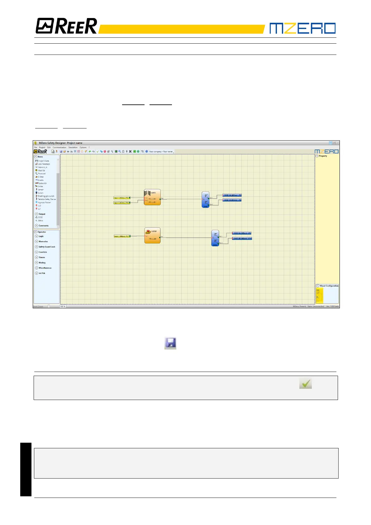
Example of a project
Figure 20 shows an example of a project in which the MZERO controller is connected to two safety
blocks (E-GATE and E-STOP).
• MZERO inputs (1,2,3) for connecting the contacts of the safety components are shown on
the left, in yellow.
• MZERO outputs (from 1 to 2) are activated according to the conditions defined in E-GATE
and E-STOP (see the E-GATE - E-STOP sections).
By clicking on a block to select it, you enable the PROPERTIES WINDOW on the right, which you
can use to configure the block activation and test parameters (see the
E-GATE - E-STOP sections).
Figure 20
• At the end of the project design stage (or at intermediate steps) you can save the current
configuration using the icon SAVE on the standard tool bar.
Project validation
➔ Now the finished project must be verified. Execute the VALIDATE command (Icon on the
standard toolbar).
If the validation is successful, a sequential number is assigned to the input and output of the
project. Then, this number is also listed in the REPORT and in the MONITOR of MZD.
Only if the validation is successful we will proceed to send the configuration.
The validation function only verifies the consistency of programming with respect to the
characteristics of the MZERO system. It does not guarantee that the device has been
programmed to meet all the safety requirements for the application.