I/O module (optional expa
Variomat Touch — 09.09.2022-Rev. C
English —
• 6 floating relay outputs (changeover)
• 3 digital inputs 230 V AC
• 3 digital inputs 24 V AC
• 2 Analogue outputs (these are not required, because they are already
contained in the Control Touch controller).
Interfaces to the controller
• RS-485
• 19.2 kbit/s
• Floating
• connection with plug or screw terminals
5.2 Settings
Danger to life from electric shock!
Risk of serious injury or death due to electric shock. Some parts of the main
board may still carry 230 V voltage even with the device physically isolated
from the 230 V power supply.
• Before you remove the covers, completely isolate the device controller
from the power supply.
• Verify that the main circuit board is voltage-free.
5.2.1 Terminator settings in RS-485 networks
Examples for the activation and deactivation of terminators in RS–485 networks.
• DIP switches 1 and 2 are located on the main board of the controller.
• Maximum length for an RS–485 connection is 1000 metres
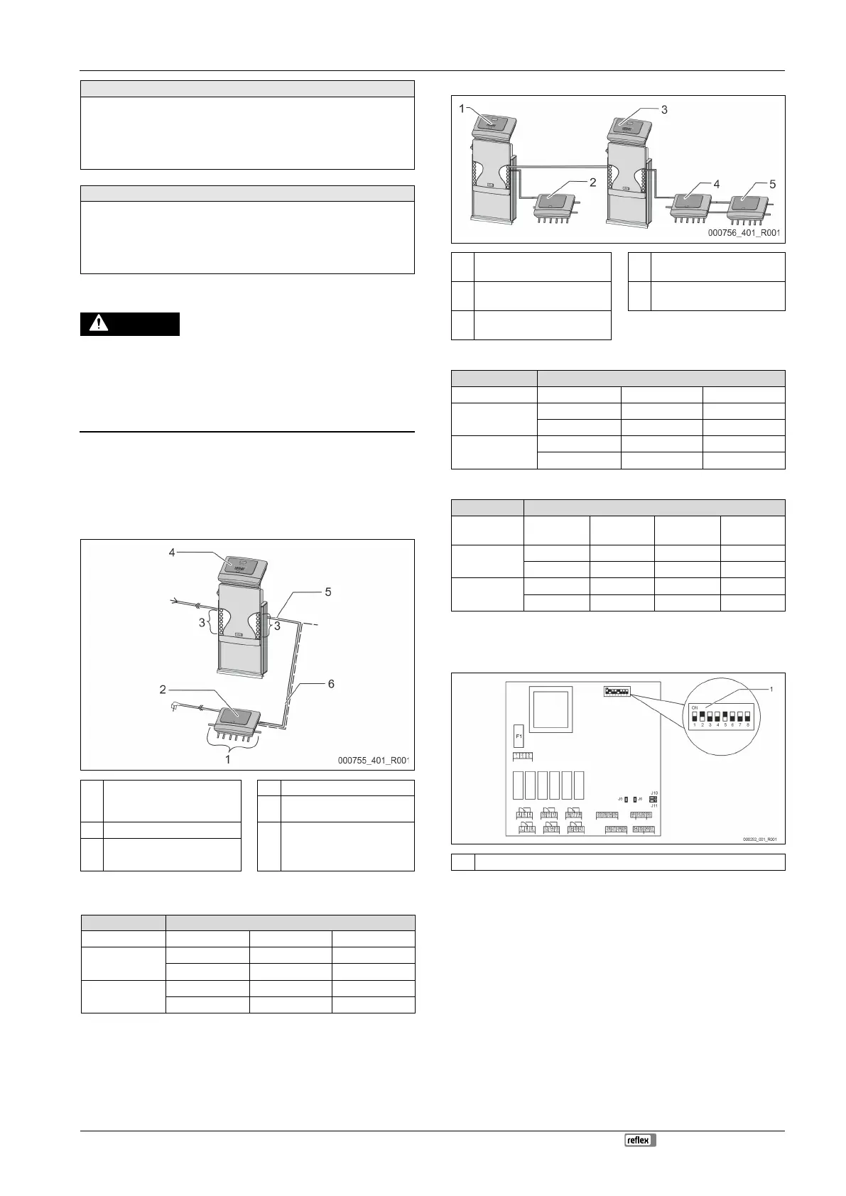
Device controller with I/O module
1
Relay outputs of the I/O
module*
4 "Control Touch" controller
5 RS-485 connection
2 I/O module 6 Optional RS-485 connection
• Master - Slave
• Field bus
3
Connections of the I/ O
conductors
* The 2 analogue outputs are not required because the Control Touch controller
already has two analogue outputs for pressure and level measurement.
Settings I/O module Control Touch
Activated X ---
Deactivated --- ---
Activated --- X
Deactivated --- ---
Device controllers and I/O module in Master-Slave function
1
Control Touch controller in
Master function
4
I/O module for the Slave
function
2
I/O module for the Master
function
5 I/O module for expansion
3
Control Touch controller in
Slave function
Master function
Settings I/O module Control Touch
Activated X ---
Deactivated --- ---
Activated --- X
Deactivated --- ---
Slave function
Settings I/O module
I/O module
for expansion
Control
Touch
Activated --- X ---
Deactivated X --- ---
Activated --- --- X
Deactivated --- --- ---
5.2.2 Setting the module address
Setting of the module address on the I/O module's main circuit board
1 DIP switch
DIP-switch position
DIP switch 1 – 4: • For setting the module address
• Variable setting to ON or OFF
DIP switch 5: • Permanently to position ON
DIP switch 6 – 8: • For internal testing
• To position OFF during operation
Use DIP switches 1 – 4 to set the module address.
Proceed as follows:
1. Pull out the mains plug of the I/O module.
2. Open the housing cover.
3. Set DIP switches 1 – 4 to position ON or OFF.
 Loading...
