R8C/20 Group, R8C/21 Group 14. Timers
Rev.2.00 Aug 27, 2008 Page 121 of 458
REJ09B0250-0200
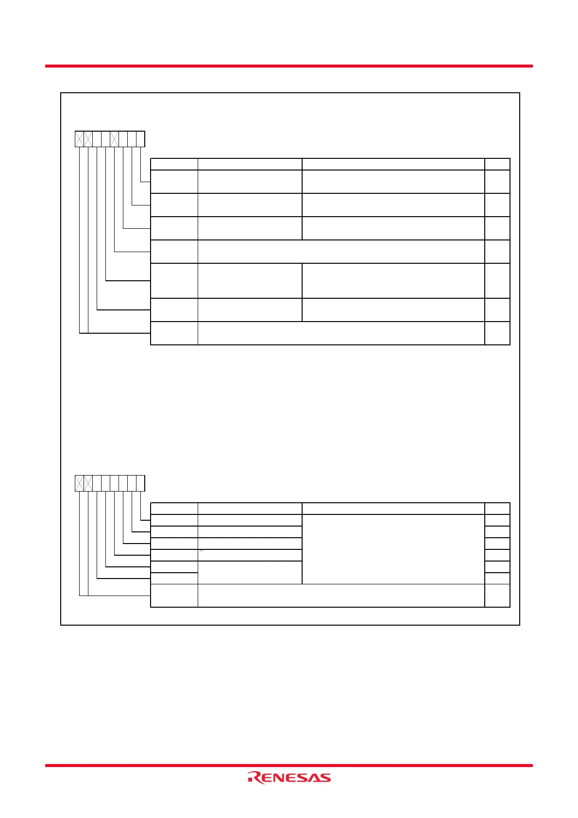
Figure 14.2 Registers TRACR and TRAIOC
Timer RA Control Re
iste
(4)
Symbol Address After Reset
TRACR
0100h 00h
Bit Symbol Bit Name Function RW
NOTES:
1.
2.
3.
4.
5.
RW
TCSTF
When the TSTOP bit is set to 1, bits TSTART and TCSTF and registers TRAPRE and TRA are set to the values after a
reset.
0 : Stops counting
1 : Counting
Nothing is assigned. If necessary, set to 0.
When read, the content is 0.
Nothing is assigned. If necessary, set to 0.
When read, the content is 0.
RO
—
(b7-b6)
—
Ref er to
14.1.6 Notes on Timer RA
.
RW
Timer RA underflow flag
(3,5)
0 : No underflow
1 : Underflow
b3 b2
When this bit is set to 1, the count is forcibly
stopped. When read, the content is 0.
—
(b3)
b1 b0b7 b6 b5 b4
RW
TUNDF
Timer RA count start bit
(1)
Timer RA count forcible stop
bit
(2)
Active edge reception
flag
(3,5)
TSTART
In pulse w idth measurement mode and pulse period measurement mode, use the MOV instruction to set the TRACR
register. If it is necessary to avoid changing the values of bits TEDGF and TUNDF, w rite 1 to them.
Set to 0 in timer mode, pulse output mode, and event counter mode.
Bits TEDGF and TUNDF can be set to 0 by w riting 0 to these bits by a program. How ever, their value remains
unchanged w hen 1 is w ritten.
0 : Stops counting
1 : Starts counting
Timer RA count status flag
(1)
TSTOP RW
—
TEDGF
0 : Active edge not received
1 : Active edge received
(end of measurement period)
Timer RA I/O Control Registe
Symbol Address After Reset
TRAIOC
0101h 00h
Bit Symbol Bit Name Function RW
RW
TIPF0
TOENA RW
TRAIO input filter select bits
TIPF1
RW
RW
Function varies depending on operation mode
—
TEDGSEL RW
TOPCR RW
TRAIO polarity sw itch bit
Nothing is assigned. If necessary, set to 0.
When read, the content is 0.
—
(b7-b6)
TRAIO output control bit
INT1
____
/TRAIO select bit
TRAO output enable bit
b7 b6 b5 b4 b3 b2
TIOSEL
b1 b0
 Loading...