R8C/20 Group, R8C/21 Group 14. Timers
Rev.2.00 Aug 27, 2008 Page 122 of 458
REJ09B0250-0200
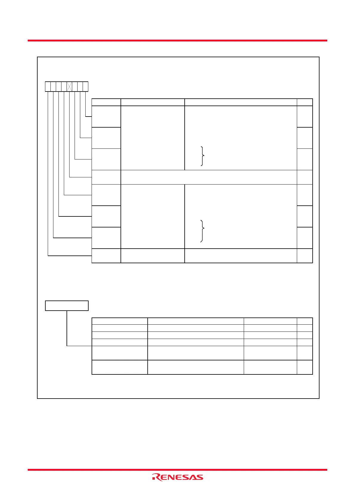
Figure 14.3 Registers TRAMR and TRAPRE
Timer RA Mode Re
ister
(1)
Symbol Address After Reset
TRAMR
0102h 00h
Bit Symbol Bit Name Function RW
NOTE:
1.
RW
—
TCK0 RW
When both the TSTART and TCSTF bits in the TRACR register are set to 0 (count stops), rew rite this register.
RW
Timer RA count source
cutoff bit
0 : Provides count source
1 : Cuts off count source
TCK2
RW
TMOD1 RW
TMOD0
Timer RA operation mode
select bits
b2 b1 b0
0 0 0 : Timer mode
0 0 1 : Pulse output mode
0 1 0 : Event counter mode
0 1 1 : Pulse w idth measurement mode
1 0 0 : Pulse period measurement mode
1 0 1 :
1 1 0 : Do not set
1 1 1 :
b7 b6 b5 b4
RW
Timer RA count source
select bits
b6 b5 b4
0 0 0 : f1
0 0 1 : f8
0 1 0 : fOCO
0 1 1 : f2
1 0 0 :
1 0 1 : Do not set
1 1 0 :
1 1 1 :
Nothing is assigned. If necessary, set to 0.
When read, the content is 0.
TMOD2
RW
TCKCUT
TCK1
b3 b2
—
(b3)
b1 b0
Timer RA Prescaler Registe
Symbol Address After Reset
TRAPRE
0103h FFh
(1)
Mode Function Setting Range RW
NOTE:
1. When the TSTOP bit in the TRACR register is set to 1, the TRA register is set to FFh.
Event Counter Mode Counts an external count source 00h to FFh RW
Counts an internal count source
00h to FFh RW
Puls e Period
Measurement Mode
Counts an internal count source
Pulse Output Mode RWCounts an internal count source 00h to FFh
RWCounts an internal count source 00h to FFh
b7
00h to FFh RW
Pulse Width
Measurement Mode
b0
Timer Mode
 Loading...