R8C/20 Group, R8C/21 Group 14. Timers
Rev.2.00 Aug 27, 2008 Page 256 of 458
REJ09B0250-0200
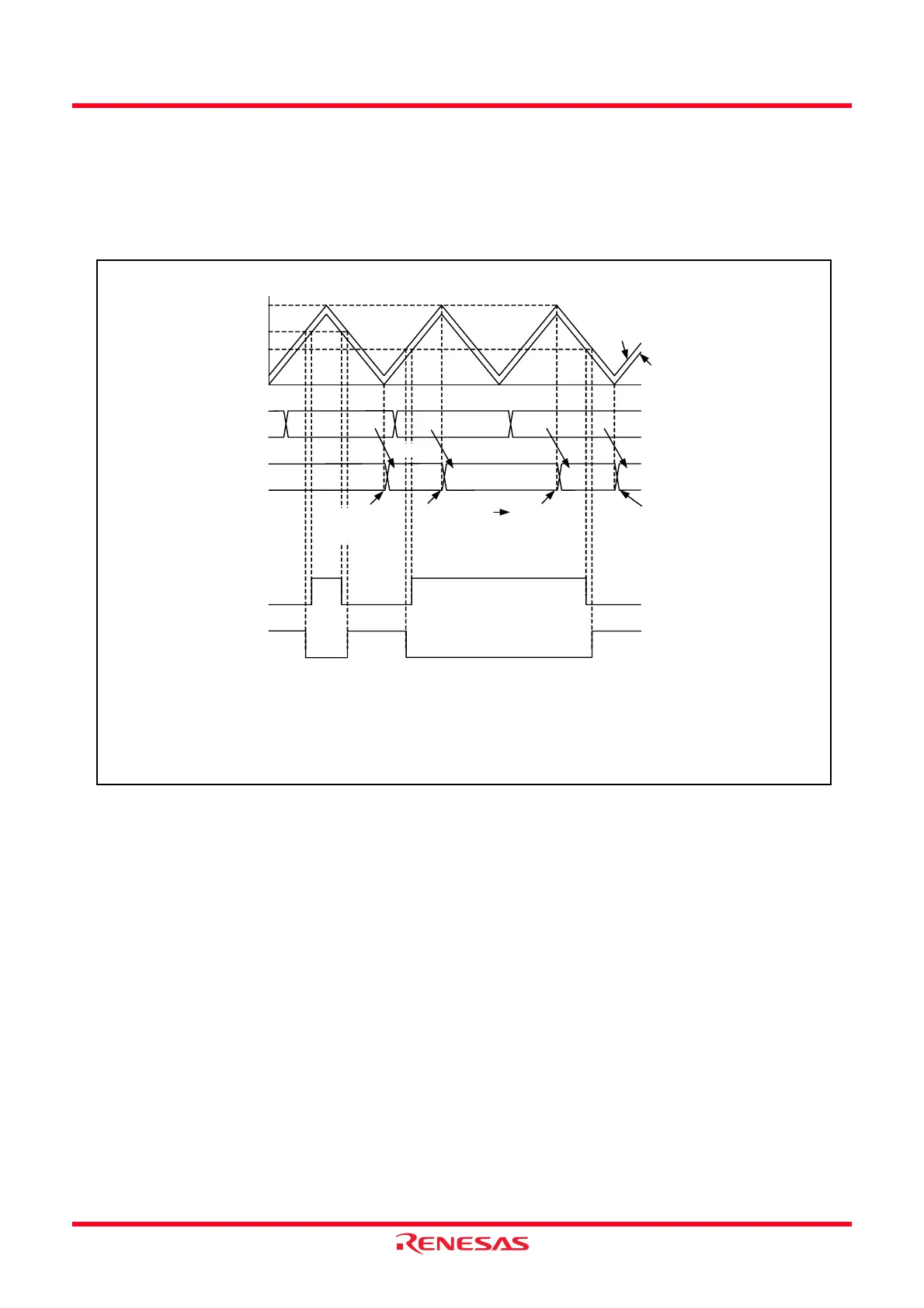
When the value in the buffer register is set to 0000h:
Transfer by the compare match in the TRD0 and TRDGRA0 registers.
And then, when setting the buffer register to 0001h or above and the smaller value than the one in the
TRDGRA0 register, and the compare match in the TRD0 and TRDGRA0 registers in the fist time after
setting, the value is transferred to the general register. After that, transfer the value with the timing selected
by the CMD1 to CMD0 bits.
Figure 14.113 Operation When Value in Buffer Register Is Set to 0000h in Complementary PWM
Mode
14.3.12.8 Count Source fOCO40M
The count source fOCO40M can be used with supply voltage VCC = 3.0 to 5.5 V. For supply voltage other than
that, do not set bits TCK2 to TCK0 in registers TRDCR0 and TRDCR to 110b (select fOCO40M as the count
source).
0000h
TRDGRD0 register
TRDIOB0 output
n1
m + 1
n 2
n1
0000h n1
0000h
n1 n1n2TRDGRB0 register
Transfer
Transfer by
compare match in
TRD0 and
TRDGRA0 registers
because content in
TRDGRD0 register
is set to 0000h.
Transfer by
compare match in
TRD0 and
TRDGRA0
registers because
of first setting to
0001h
≤ n1 < m
Transfer with timing
set by CMD1 to
CMD0 bits
TRDIOD0 output
m: Setting Value in TRDGRA0 Register
The above applies to the following conditions:
• The CMD1 to CMD0 bits in the TRDFCR register are set to 10b.
(Data in the buffer register is transferred at the underflow in the TRD1 register in PWM mode.)
• Both the OLS0 and OLS1 bits in the TRDFCR register are set to “1” (active “H” for normal-phase and counter-phase).
Count value in TRD0 register
Count value in TRD1 register
Transfer with timing
set by CMD1 to
CMD0 bits
Transfer
Transfer Transfer
 Loading...