R8C/20 Group, R8C/21 Group 16. Clock Synchronous Serial Interface
Rev.2.00 Aug 27, 2008 Page 299 of 458
REJ09B0250-0200
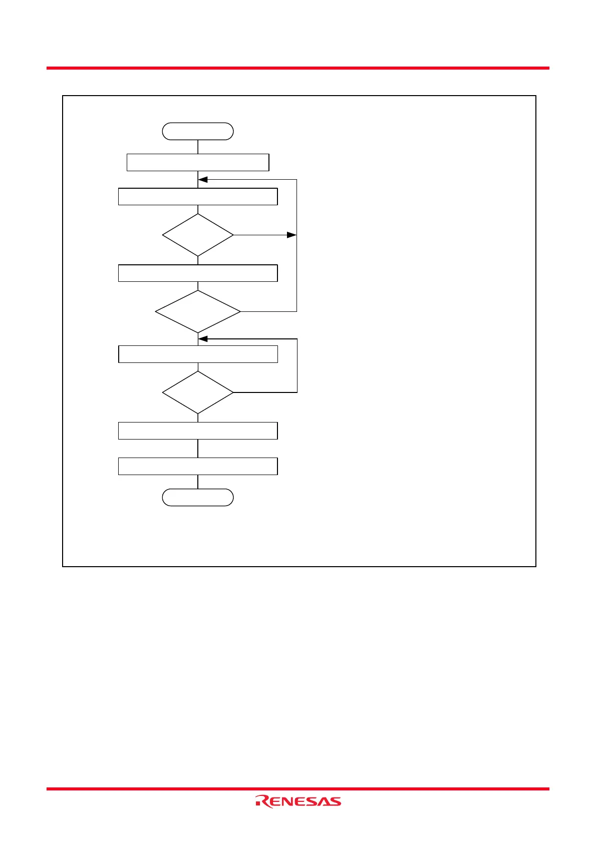
Figure 16.14 Sample Flowchart of Data Transmission (Clock Synchronous Communication Mode)
Start
Initialization
Read TDRE bit in SSSR register
SSSR register TEND bit ← 0
(1)
End
TDRE = 1 ?
Write transmit data to SSTDR register
Data transmit
continued?
Read TEND bit in SSSR register
TEND = 1 ?
No
Yes
Yes
No
No
Yes
SSER register TE bit ← 0
(1)
(2)
(3)
(1) After reading the SSSR register and confirming
that the TDRE bit is set to 1, write the transmit
data to the SSTDR register. When write the
transmit data to the SSTDR register, the TDRE bit
is automatically set to 0.
(2) Determine whether data transmit is continued
(3) When the data transmit is completed, the TEND
bit is set to 1. Set the TEND bit to 0 and the TE bit
to 0 and complete transmit mode.
NOTE:
1. Write 0 after reading 1 to set the TEND bit to 0.
 Loading...