R8C/20 Group, R8C/21 Group 16. Clock Synchronous Serial Interface
Rev.2.00 Aug 27, 2008 Page 316 of 458
REJ09B0250-0200
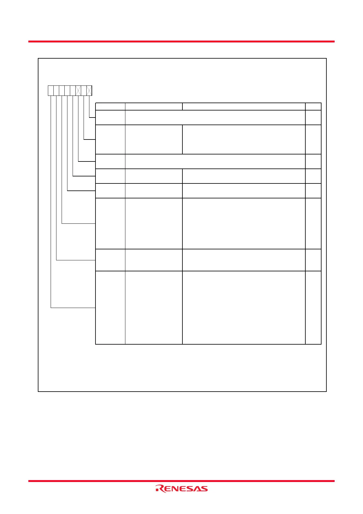
Figure 16.25 ICCR2 Register
IIC Bus Control Register 2
Symbol Address After Reset
ICCR2
00B9h 01111101b
Bit Symbol Bit Name Function RW
NOTES:
1.
2.
3.
4.
—
(b0)
Nothing is assigned. If necessary, set to 0.
When read, the content is 1.
—
IICRST RW
RO
RW
—
IIC control part reset bit
b0b3 b2 b1b7 b6 b5 b4
When hang-up occurs due to communication failure
during I
2
C bus interface operation and w rite 1, reset
control part of I
2
C bus interface w ithout setting port
and initializing register.
—
(b2)
Nothing is assigned. If necessary, set to 0.
When read, the content is 1.
SCLO
SCL monitor flag 0 : SCL pin is set to “L”
1 : SCL pin is set to “H”
o not w r
te
ur
ng trans
er operat
on.
SDAOP
SDAO RW
When read
0 : SDA pin output is held “L”
1 : SDA pin output is held “H”
When w rite
(1,2)
0 : SDA pin output is changed to “L”
1 : SDA pin output is changed to high-impedance
(“H” output is external pull-up resistor)
SDA output value control
bit
SDAO w rite protect bit When rew rite to SDAO bit, w rite 0 simultaneously.
(1)
When read, its content is
1.
BBSY
Bus busy bit
(4)
SCP
Start / stop condition
generation disable bit
When w rite to BBSY bit, w rite 0 simultaneously.
(3)
When read, its content is 1.
Writing 1 is disabled.
RW
When read
0 : Bus is in released state
(SDA signal changes from “L” to “H” w hile SCL
signal is in “H” state)
1 : Bus is in occupied state
(SDA signal changes from “H” to “L” w hile SCL
signal is in “H” state)
When w rite
(3)
0 : Generates stop condition
1 : Generates start condition
RW
s
t
s
sa
e
w
en t
e c
oc
sync
ronous ser
a
ormat
s use
.
This bit is enabled in master mode. When w rite to the BBSY bit, w rite 0 to the SCP bit using the MOV instruction
simultaneously. Execute the same w ay w hen the start condition is regenerating.
en w r
t
ng to t
e
t, w r
te
to t
e
t us
ng t
e
nstruct
on s
mu
taneous
y.
 Loading...