R8C/20 Group, R8C/21 Group 17. Hardware LIN
Rev.2.00 Aug 27, 2008 Page 355 of 458
REJ09B0250-0200
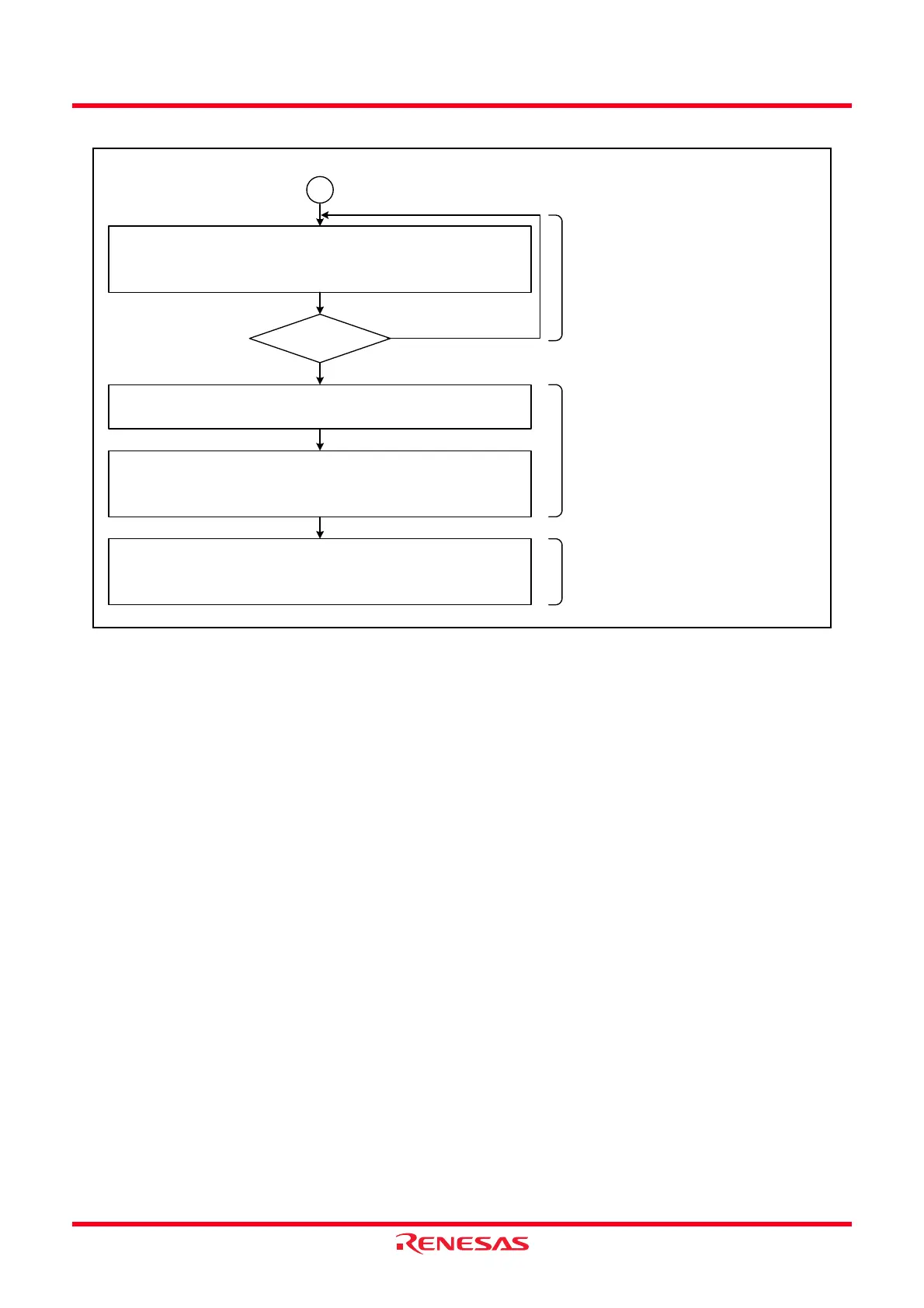
Figure 17.10 Example of Header Field Reception Flowchart (3)
Hardware LIN Read the Synch Field measurement-
completed flag
SFDCT flag in the LINST register
UART0 Set the UART0 communication rate
U0BRG register
Communication via UART0
(The SBDCT flag is set when timer
RA counter underflows upon
reaching the terminal count.)
B
SFDCT = 1?
YES
UART0 Communication via UART0
Clock asynchronous serial interface (UART) mode
Receive ID field
NO
Hardware LIN measure the Synch
Field.
The interrupt of timer RA may be
used.
(The SBDCT flag is set when the
timer RA counter underflows upon
reaching the terminal count.)
When the SBE bit in the LINCR
register is set to 1 (Unmasked after
Synch Field measurement is
completed), timer RA may be used
in timer mode after the SFDCT bit
in the LINST register is set to 1.
Set a communication rate based on
the Synch Field measurement
result.
YES
Timer RA Set the Synch Break width back again
TRAPRE register
TRA register
 Loading...