R8C/20 Group, R8C/21 Group 20. Electrical Characteristics
Rev.2.00 Aug 27, 2008 Page 412 of 458
REJ09B0250-0200
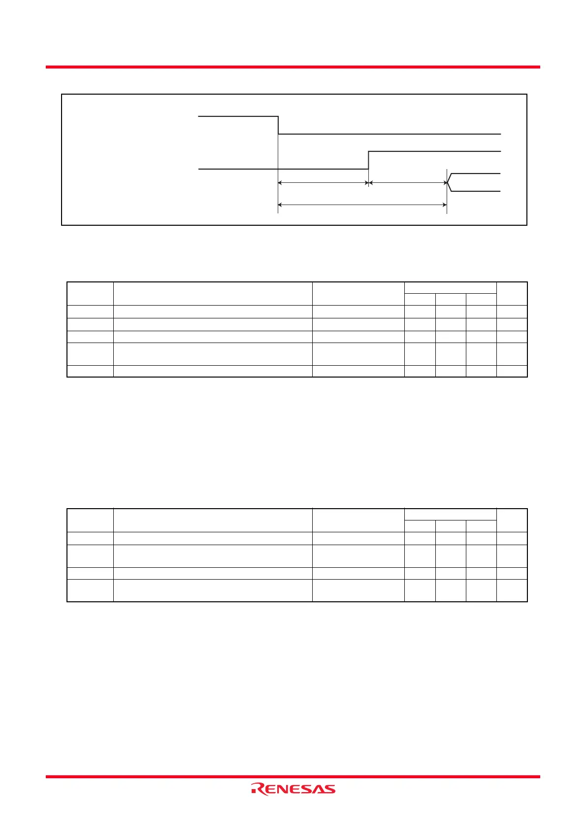
Figure 20.2 Time delay until Suspend
NOTES:
1. The measurement condition is V
CC = 2.7 V to 5.5 V and Topr = -40°C to 85°C (J version) / -40°C to 125°C (K version).
2. Necessary time until the voltage detection circuit operates when setting to 1 again after setting the VCA26 bit in the VCA2
register to 0.
3. Hold V
det2 > Vdet1.
4. This parameter shows the voltage detection level when the power supply drops. The voltage detection level when the power
supply rises is higher than the voltage detection level when the power supply drops by approximately 0.1 V.
5. Time until the voltage monitor 1 reset is generated after the voltage passes V
det1 when VCC falls. When using the digital filter,
its sampling time is added to t
d(Vdet1-A). When using the voltage monitor 1 reset, maintain this time until VCC = 2.0 V after the
voltage passes V
det1 when the power supply falls.
NOTES:
1. The measurement condition is V
CC = 2.7 V to 5.5 V and Topr = -40°C to 85°C (J version) / -40°C to 125°C (K version).
2. Time until the voltage monitor 2 reset/interrupt request is generated since the voltage passes V
det2.
3. Necessary time until the voltage detection circuit operates when setting to 1 again after setting the VCA27 bit in the VCA2
register to 0.
4. Hold V
det2 > Vdet1.
5. When using the digital filter, its sampling time is added to t
d(Vdet2-A). When using the voltage monitor 2 reset, maintain this
time until V
CC = 2.0 V after the voltage passes Vdet2 when the power supply falls.
Table 20.6 Voltage Detection 1 Circuit Electrical Characteristics
Symbol Parameter Condition
Standard
Unit
Min. Typ. Max.
V
det1
Voltage detection level
(3, 4)
2.70 2.85 3.00 V
t
d(Vdet1-A)
Voltage monitor 1 reset generation time
(5)
− 40 200 µs
− Voltage detection circuit self power consumption VCA26 = 1, VCC = 5.0 V − 0.6 −µA
t
d(E-A) Waiting time until voltage detection circuit operation
starts
(2)
−−100 µs
Vccmin MCU operating voltage minimum value 2.70
−−V
Table 20.7 Voltage Detection 2 Circuit Electrical Characteristics
Symbol Parameter Condition
Standard
Unit
Min. Typ. Max.
V
det2
Voltage detection level
(4)
3.3 3.6 3.9 V
t
d(Vdet2-A) Voltage monitor 2 reset/interrupt request generation
time
(2, 5)
− 40 200 µs
− Voltage detection circuit self power consumption VCA27 = 1, VCC = 5.0V − 0.6 −µA
t
d(E-A) Waiting time until voltage detection circuit operation
starts
(3)
−−100 µs
FMR46
Suspend request
(Maskable interrupt request)
Fixed time
td(SR-SUS)
Clock-dependent time
Access restart
 Loading...