R8C/20 Group, R8C/21 Group 20. Electrical Characteristics
Rev.2.00 Aug 27, 2008 Page 419 of 458
REJ09B0250-0200
NOTES:
1. V
CC = 2.7 to 5.5 V, VSS = 0V at Topr = -40 to 85°C (J version) / -40 to 125°C (K version), unless otherwise specified.
2. 1t
CYC = 1/f1(s)
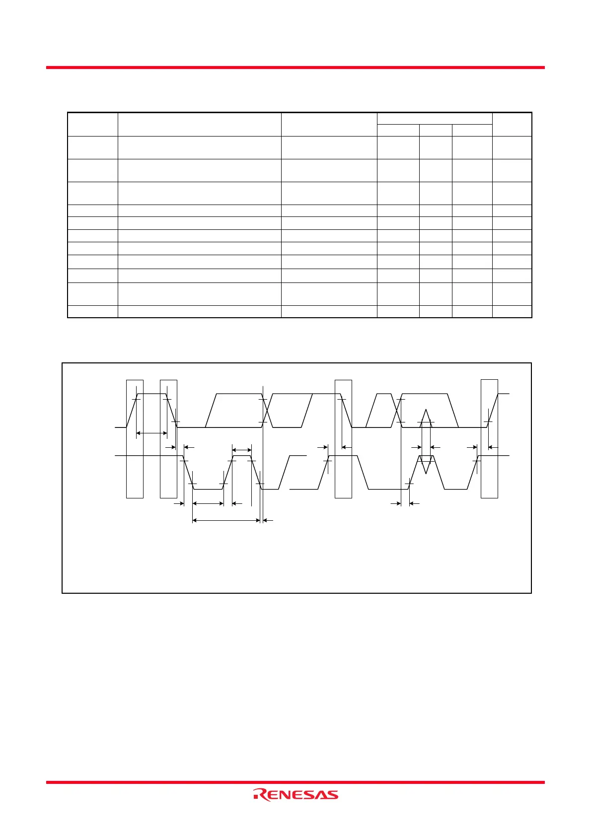
Figure 20.7 I/O Timing of I
2
C Bus Interface
Table 20.13 Timing Requirements of I
2
C Bus Interface
(1)
Symbol Parameter Conditions
Standard
Unit
Min. Typ. Max.
t
SCL SCL input cycle time 12tCYC +
600
(2)
−− ns
t
SCLH SCL input “H” width 3tCYC +
300
(2)
−− ns
t
SCLL SCL input “L” width 5tCYC +
300
(2)
−− ns
t
sf SCL, SDA input falling time −−300 ns
t
SP SCL, SDA input spike pulse rejection time −−
1tCYC
(2)
ns
t
BUF SDA input bus-free time
5t
CYC
(2)
−− ns
t
STAH Start condition input hole time
3t
CYC
(2)
−− ns
t
STAS
Retransmit start condition input setup time
3t
CYC
(2)
−− ns
t
STOP
Stop condition input setup time
3t
CYC
(2)
−− ns
t
SOAS Data input setup time 1tCYC +
20
(2)
−− ns
t
SDAH Data input hold time 0 −− ns
SDA
SCL
tBUF
VIH
VIL
P
(2)
S
(1)
tSTAH
tSCLH
tSCLL
tSf tSr
tSCL
tSDAH
Sr
(3)
P
(2)
tSDAS
tSTAS
tSP
tSTOP
NOTES:
1. Start condition
2. Stop condition
3. Retransmit “Start” condition
 Loading...