R8C/20 Group, R8C/21 Group 10. Clock Generation Circuit
Rev.2.00 Aug 27, 2008 Page 76 of 458
REJ09B0250-0200
10.4.2.4 Exiting Wait Mode
The MCU exits wait mode by a hardware reset or peripheral function interrupt. When using a hardware reset to
exit wait mode, set the ILVL2 to ILVL0 bits for the peripheral function interrupts to 000b (interrupts disabled)
before executing the WAIT instruction.
The peripheral function interrupts are affected by the CM02 bit. When the CM02 bit is set to 0 (peripheral
function clock does not stop in wait mode), all peripheral function interrupts can be used to exit wait mode.
When the CM02 bit is set to 1 (peripheral function clock stops in wait mode), the peripheral functions using the
peripheral function clock stop operating and the peripheral functions operated by external signals can be used
to exit wait mode.
Table 10.3 lists Interrupts to Exit Wait Mode and Usage Conditions.
Figure 10.9 shows the Time from Wait Mode to Interrupt Routine Execution.
When using a peripheral function interrupt to exit wait mode, set up the following before executing the WAIT
instruction.
(1) Set the interrupt priority level to the ILVL2 to ILVL0 bits in the interrupt control register of the
peripheral function interrupts to use for exiting wait mode. Set the ILVL2 to ILVL0 bits of the
peripheral function interrupts not to use for exiting wait mode to 000b (disables interrupt).
(2) Set the I flag to 1.
(3) Operate the peripheral function to use for exiting wait mode.
When exiting by a peripheral function interrupt, the time (number of cycles) between interrupt request
generation and interrupt routine execution is determined by the settings of the FMSTP bit in the FMR0 register
as described in Figure 10.9.
The CPU clock, when exiting wait mode by a peripheral function interrupt, is the same clock as the CPU clock
when the WAIT instruction is executed.
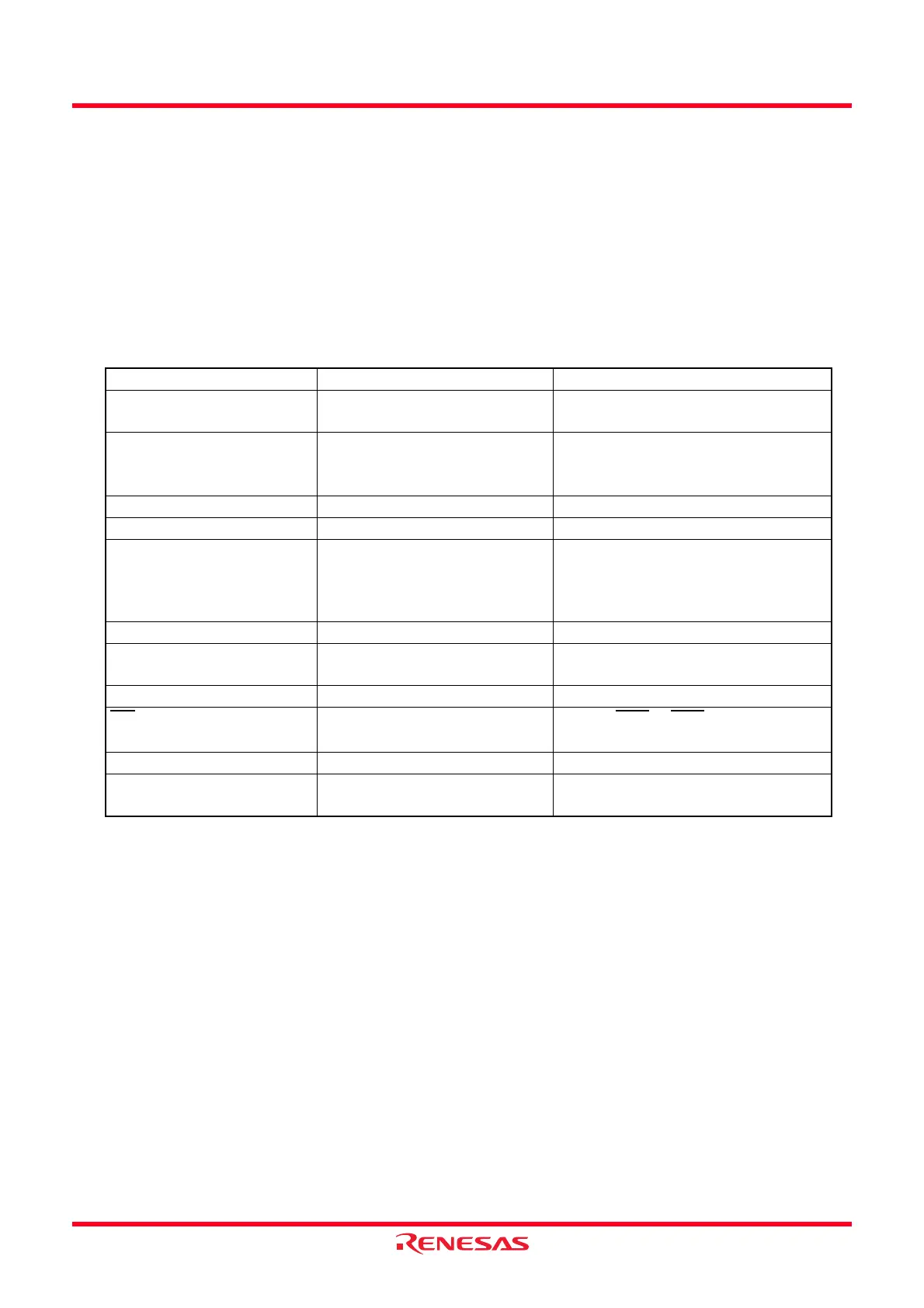
Table 10.3 Interrupts to Exit Wait Mode and Usage Conditions
Interrupt CM02 = 0 CM02 = 1
Serial Interface Interrupt Usable when operating with
internal or external clock
Usable when operating with external
clock
Clock Synchronous Serial I/O
with Chip Select Interrupt /
I
2
C Bus Interface Interrupt
Usable in all modes − (Do not use)
Key Input Interrupt Usable Usable
A/D Conversion Interrupt Usable in one-shot mode − (Do not use)
Timer RA Interrupt Usable in all modes Can be used if there is no filter in event
counter mode.
Usable by selecting fOCO as count
source.
Timer RB Interrupt Usable in all modes − (Do not use)
Timer RD Interrupt Usable in all modes Usable by selecting fOCO40M as
count source
Timer RE Interrupt Usable in all modes − (Do not use)
INT
Interrupt
Usable
Usable (INT0 to INT3 can be used if
there is no filter.)
Voltage Monitor 2 Interrupt Usable Usable
Oscillation Stop Detection
Interrupt
Usable − (Do not use)
 Loading...