36
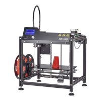
InstallationoftheX-motortotherightguidecarriageplate
1x guide carriage plate right
1x actuator with installed sprocket
3x cylinder head screw M3x12 black
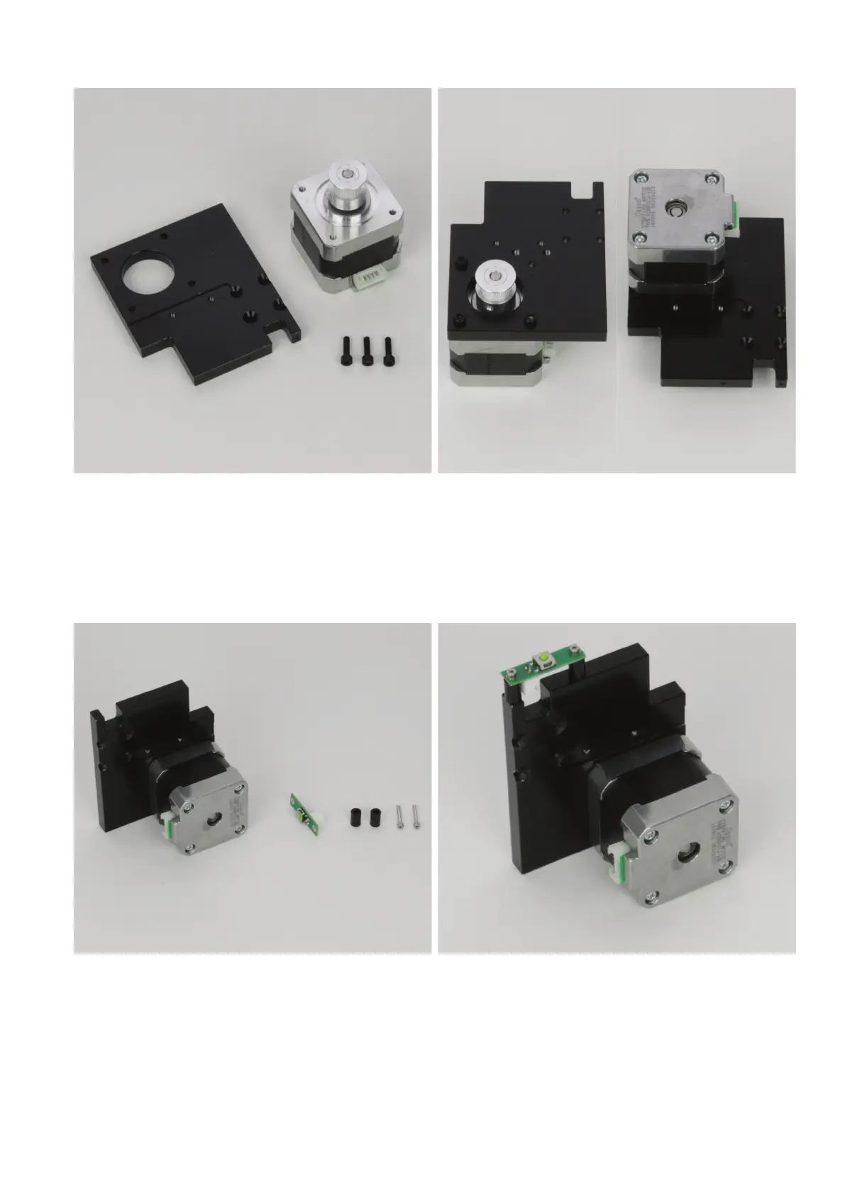
Install the motor with the 4 cylinder-head screws to the right guide
carriageplate(leftgure).Themotormustbeonthesamesideasthe
slotfortheguiderail(rightgure).Themotorplugmustbealignedas
inthegure(rightgure=recessed-headboresontop).
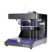
Installationofthelimitswitchtotherightguidecarriageplate
1x right guide carriage plate with installed actuator
1x limit switch PCB
2xspacer9mm(diameterinside3mm)
2x cylinder head screw M2x16
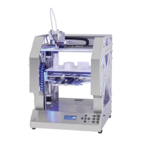
Install a limit switch PCB with the two cylinder-head screws M2x16 at
the right guide carriage plate.
A spacer must be used between each guide carriage plate and the
limit switch PCB.
Optionally, the screws can be secured with threadlocker varnish.