45
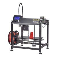
Turninginofthethreadedpin
1x extruder holder
1x threaded pin M4x8
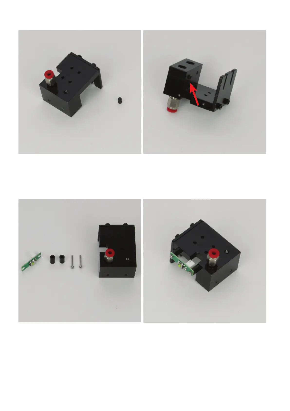
Screw the threaded pin into the bore by the quick closure from behind.
Only screw in the threaded pin loosely. It must not protrude into the
bore for the extruder yet.
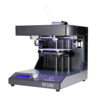
Assemblyofthelimitswitchandtheextruderholder
1x limit switch PCB
2xspacer9mm(diameterinside3mm)
2x cylinder head screw M2x16
1x extruder holder
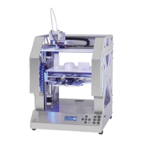
Mount the limit switch PCB on the extruder holder with the two cylin-
der-head screws M2x16 on the left, at the cut-out.
A spacer must be used between each extruder holder and the limit
switch PCB.
Optionally, the screws can be secured with threadlocker varnish.