74
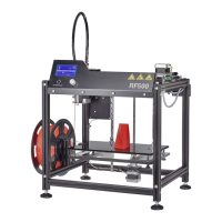
Take 3 adhesive sockets and glue them to the printer as illustrated.
Degreasetheadhesiveareasrst.
Take3cableties(142mm)andfastenthecablestrandlooselytothe
adhesive sockets with them.
If the cable is too tense then, you may need to cut off a piece of the
lamenttubesothatthecablescanbeplacedcleanly(seenextg-
ure). Cut off only a small piece at a time!
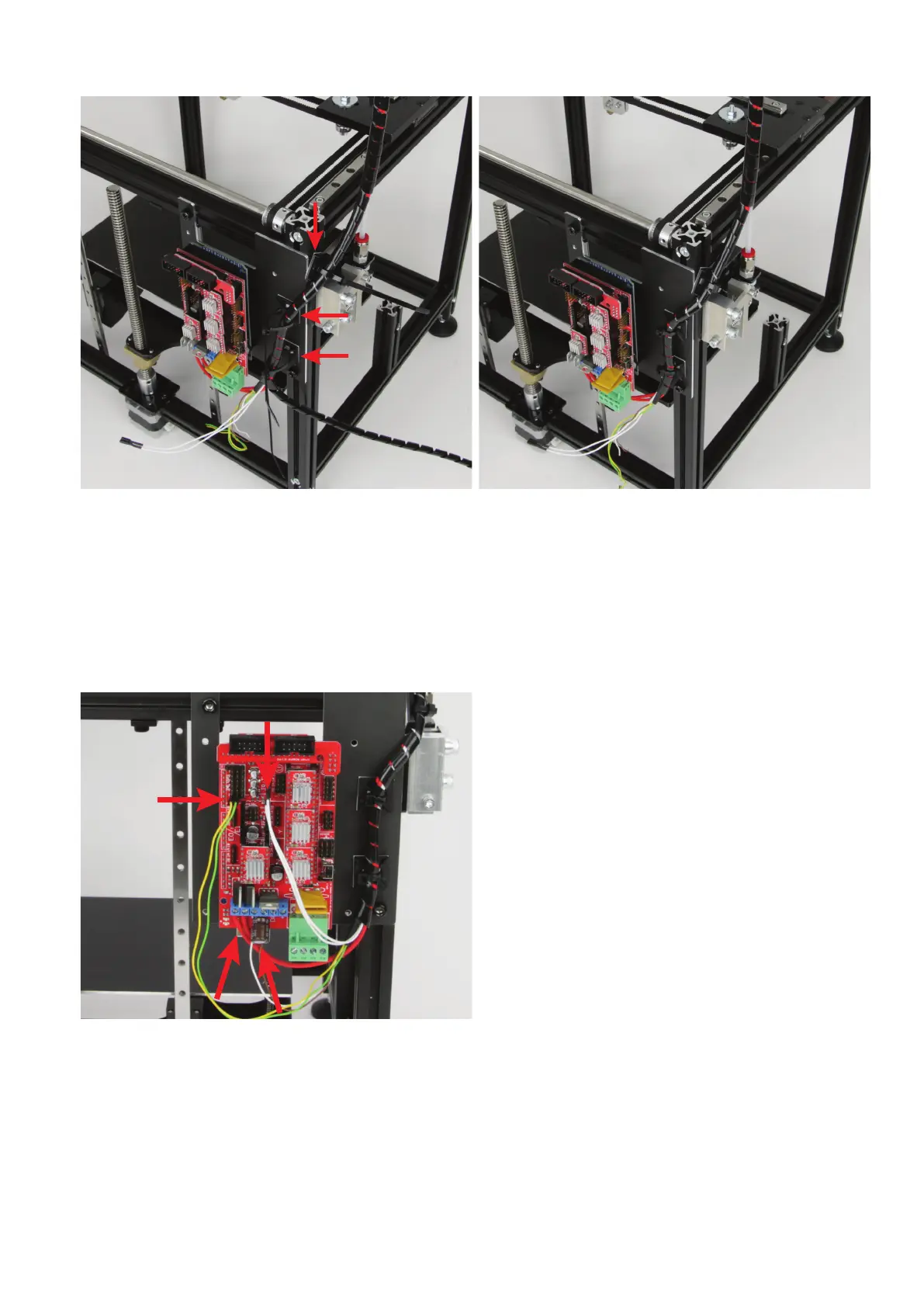
When the length is correct, tighten the cable ties at the cable strand.
Nowsecurethecableofthefanwiththeshortcabletie(99mm)tothe
cableoftheXlimitswitchattheextruderholder.
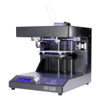
Now connect the other lines to the main PCB.
Connect the two open lines of the fan, brown and white, to the con-
nection "D9". The brown line is plus/+! The elco must be connected
in parallel as well here. Ensure correct polarity! The minus pole at the
elco is marked with a white dash. This side must go into the terminal
where the white line of the fan connected.
Connect the plug to the connection "T0" of the main PCB with the
twowhitelinesofthetemperaturesensor(cable03).Thepolarityis
irrelevant for this.
Connect the cable with the yellow and green line to the two pins that
are marked with "LimitswitchX" in the connection plan. The polarity
does not matter in this cable either.