www.resourcedm.com
Revision 2.3 Page 6 of 72
Commissioning & Service Guide DMTouch
Warning
Please Note
The specifications of the product detailed on this
Set-Up Guide may change without notice. RDM
Ltd. shall not be liable for errors or for incidental
or consequential damages, directly and indirectly,
in connection with the furnishing, performance or
misuse of this product or document.
Ensure that all power is
switched off before
installing or maintaining
this product
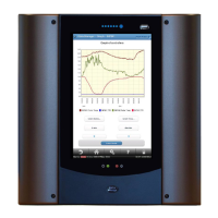
Layout
If a layout diagram has been loaded during commissioning, then a screen similar to below will appear as the home page. Clicking on a
device or bay, will auto zoom to that area.
The layout screen on the right gives an over-view of the site layout. The individual devices are colour coded to show their respective
states.
Colours defining device states are: -
Red Alarm
Blue Normal
Yellow Defrost
Green Case Off
Orange Alarm Inhibit
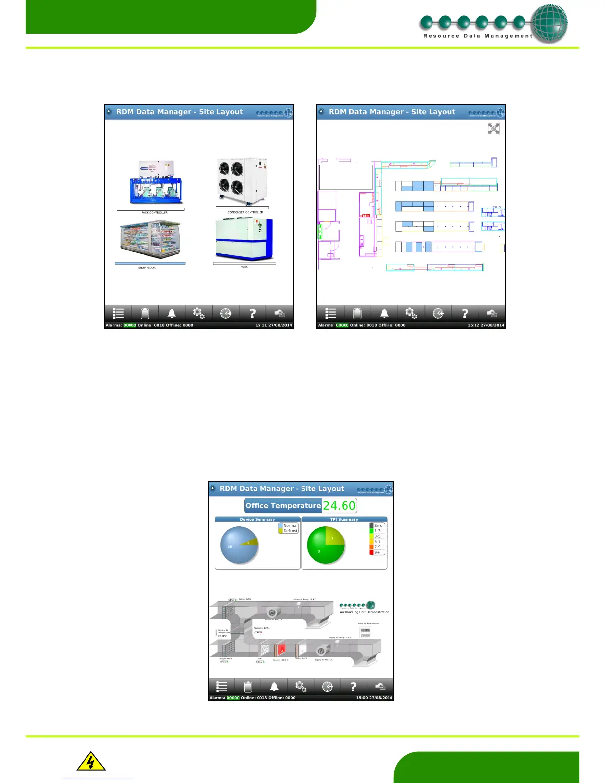
The user can also create their own images using the RDM Layout Editor 2 program that can be displayed on the DMTouch layout
screen. Below is an example of image created for an air handling unit. Contact Technical Support for further information on Layout
Editor 2.