4.3 Process Data Setting Range
The range of both output and input process data is listed in the table below. If
the setting values exceed the range, "FPC-" error will be triggered.
The output process data list includes the cyclic data objects that can be trans-
ferred from controller to peripheral devices.
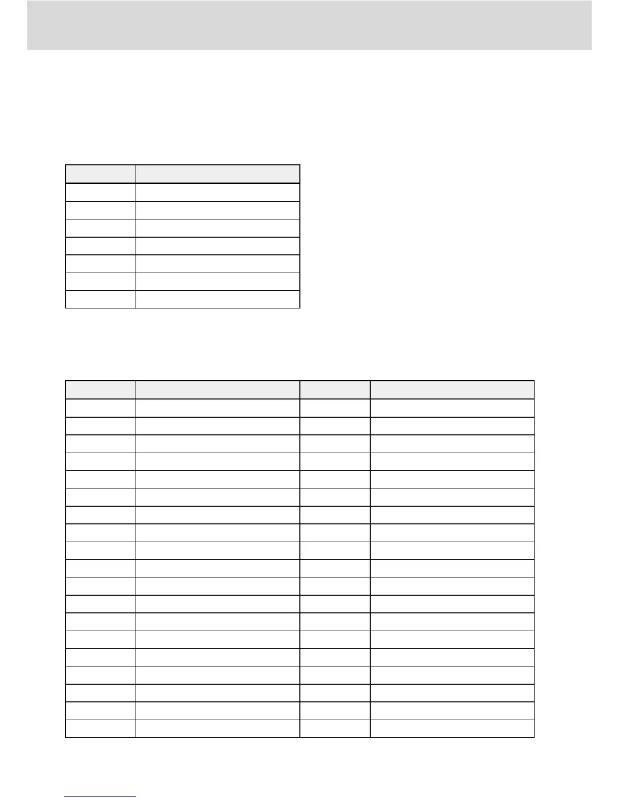
Code Name
H0.00 Control word
H0.10 Frequency command
H0.40 Dummy PZD
F0.20 ASF command01
F0.21 ASF command02
F0.22 ASF command03
F0.23 ASF command04
Tab. 4-5: Output process data parameter list
And the input process data list includes the cyclic data objects that can be
transferred from peripheral devices to controller. Normally, the monitoring data
are collected by controller.
Code Name Code Name
H0.01 Status word d0.43 I/O card digital input
d0.00 Output frequency d0.45 DO1 output
d0.01 Actual speed d0.47 I/O card EDO output
d0.02 Setting frequency d0.50 Pulse input frequency
d0.03 Setting speed d0.55 Pulse output frequency
d0.04 User-defined setting speed d0.60 Relay output
d0.05 User-defined output speed d0.62 I/O card relay output
d0.10 Output voltage d0.63 Relay card output
d0.11 Output current d0.70 PID reference engineering value
d0.12 Output power d0.71 PID feedback engineering value
d0.13 DC-bus voltage d0.80 ASF Display00
d0.16 Output torque d0.81 ASF Display01
d0.17 Setting torque d0.82 ASF Display02
d0.20 Power module temperature d0.83 ASF Display03
d0.21 Actual carrier frequency d0.84 ASF Display04
d0.22 Control stage running time d0.85 ASF Display05
d0.23 Power stage running time d0.86 ASF Display06
d0.30 AI1 input d0.87 ASF Display07
d0.31 AI2 input d0.88 ASF Display08
Bosch Rexroth AG
General Configuration
Multi-Ethernet Card
10/61
DOK-RCON0*-XFCX610*MUL-IT02-EN-P