Rexroth IndraDyn A Connection Techniques 8-7
• “Electromagnetic compatibility (EMC)...” MNR R911259740
• documentation of the motor used
• documentation of the drive device used
• documentation “Rexroth Connection Cables”, MNR R911282688.
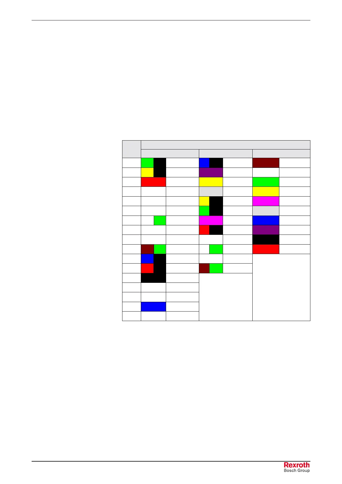
8.7 Encoder Connection
The connection of the encoder to IndraDyn A motors is made via a 10-
pole, 12-pole or 17-pole flange socket at the motor housing. See the
following chart for the connector assignment:
Encoder option
PIN C0 M0 / S0 S2, M2
1
GN BK
A+
BU BK
A-
BN
+US
2
YE BK
A-
VI
SCL
WH
GND
3
RD
R+
YE
F Sample
GN
A+
4free
GY
SD in
YE
A-
5free
YE BK
B+
PK
B+
6free
GN BK
B-
GY
B-
7
WH GN
0V
PK
SD out
BU
data+
8free
RD BK
A+
VI
data-
9 free free
BK
clk+
10
BN GN
+V
WH GN
0V
RD
clk-
11
BU BK
B+ free
12
RD BK
B-
BN GN
+V
13
BK
R-
14 free
15
WH
0V Sense
16
BU
+5V Sense
17 free
not applicable
not applicable
Fig. 8-10: Overview of encoder connection layouts

 Loading...

