4-70 Technical Data Rexroth IndraDyn A
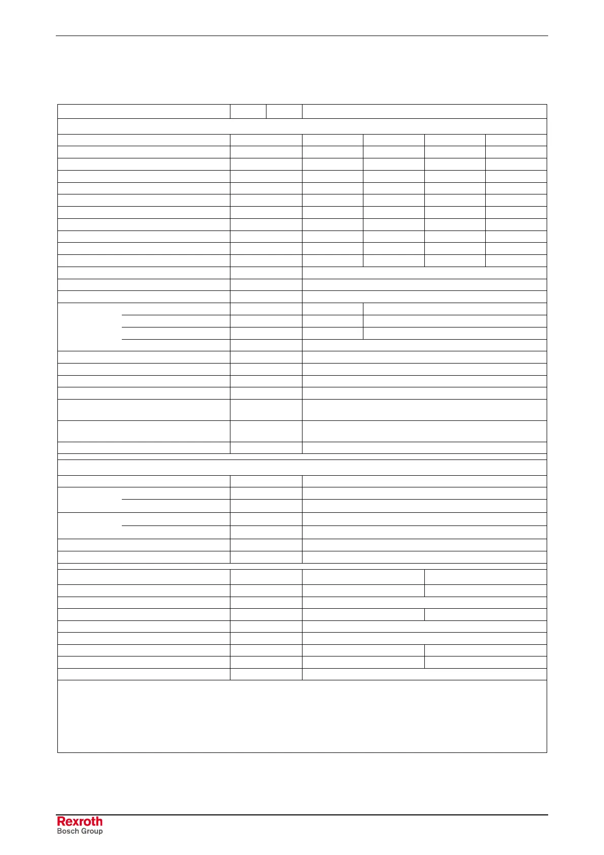
4.21 Technical Data Sheet for MAF180C
Description Symbol Unit MAF180C
Motor data
1
)
Winding
0050 0100 0150 0200
Rated torque M
nenn
Nm
435 390 365
318
Rated speed n
nenn
rpm
500 1000 1500 2000
Rated power P
nenn
kW
22.8 40.8 57.3 66.6
Rated current I
nenn
A
49.8 90.7 128.8 154
Continuous torque at standstill M
n1
Nm
- 435 390 336
Derating speed n
1
rpm
- 500 1000 1500
Continuous current at standstill I
n1
A
- 99.7 136.1 160.5
Maximum speed M
max
Nm
986 957 858 739
Torque constant at 20°C K
M_nenn
Nm/A
9.61 4.67 3.11 2.39
Min. cross section of power cable
2
) A mm²
10 25 2x16 2x25
Number of pole pairs p
3
Moment of inertia of rotor
3
)J
rot
kgm²
0.49
Motor mass
3
)mkg
312
- Standard
n
max
rpm
3000
6000
- coupling attachment
n
max
rpm
3000 4200
- reinforced
n
max
rpm
3000 6000
Maximum
speed with
bearing...
- High-speed
n
max
rpm
not available
Thermal time constant T
th
min
25
Duty cycle time (S6-44%) T
C
min
i.p.
Noise level
4
)p
Schall
dB(A)
75 (+3)
Permissible ambient temperature T
um
°C
0....+40
Permissible storage and transport
temperature T
lager
°C
-20....+80
Insulation class according to
DIN VDE 0530-1
F
International Protection class
IP65
Liquid cooling
5
)
Power loss to be dissipated P
V
kW 4.5
Cooling agent inlet T
ein
°C +10....+40
Cooling agent
temperature
Permissible increase at P
V
∆T
diff
K10
without fast coupling
∆p
diff
bar 0.6
Decompression
at Q
min
with fast coupling
∆p
diff
bar 1.2
Required flow of coolant at P
V
Q
min
l/min 6.6
max. system pressure p
max
bar 3
Holding brake (optional) Electrically-clamped Electrically-released
Transmittable torque M
4
Nm 300 240
Connection voltage U
Br
V DC 24 ± 10 %
Rated current I
Br
A 2 1.87
Moment of inertia J
Br
kgm² 0.0188
Max. permissible braking energy W
max
Ws 70000
Disengagement time t
2
ms 90 300
Engagement time t
1
ms 150 30
Mass of brake m kg 25
1
) Values determined according to IEC 60034-1. Current and voltage specified as root-mean-square values.
2
) Rated for cable assemblies with current carrying capacity according to VDE0298-4 (1992) and installation type B2
according to EN 60204-1 (1993) at 40°C ambient temperature.
3
) Values without holding brake.
4
) in 1 m distance, with PWN = 4kHz
5
) Data refer to water as a cooling agent. If using other coolant, re-calculate the data.
Observe instructions on coolant inlet temperature in chapter 9.
Fig. 4-96: Data Sheet MAF180C

 Loading...

