9-14 Application Notes Rexroth IndraDyn A
Before startup and during operation specifications, the brake function
must be tested with the ”brake command” function. By applying a small
amount of motor torque, the brake is checked for slippage. Additional
information and specifications of this function may be found in the
ECODRIVE firmware functional descriptions.
Selecting Holding Brakes
Brakes are either electrically-clamped or electrically-released. Due to
functional differences, different brakes should be used for main-spindle
and for servo-axes. Observe the safety requirements during the system
design.
t
1
2
U
n
[V]
0
24
U
n
[V]
0
24
t
1
t
2
t
1
t
2
t
brake.EPS
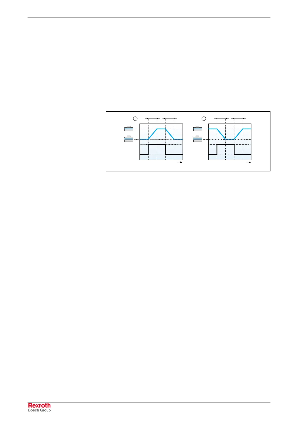
(1): Electrically-clamped brake
(2): Electrically-released brake
t
1
:
Clamp delay
t
2
: Releasing time
Fig. 9-17: Holding brake diagram
Main Spindle Applications
An electrically-clamped holding brake can be used to lock a main
spindle during standstill and when the control ”controller enable” signal is
off, e.g. when a tool change is performed without a closed position loop.
⇒ Clamp the motor only at standstill, i.e. after the controller has signaled
the motor is at standstill.
An electrically-released holding brake should not be used on main
spindles. Unintentional clamping of the holding brake at high motor
speeds can lead to extreme deterioration or even demolition of the brake
(e.g. in the case of power loss or wire breakage).
Functional test
Electrically-clamped Holding
Brake

 Loading...

