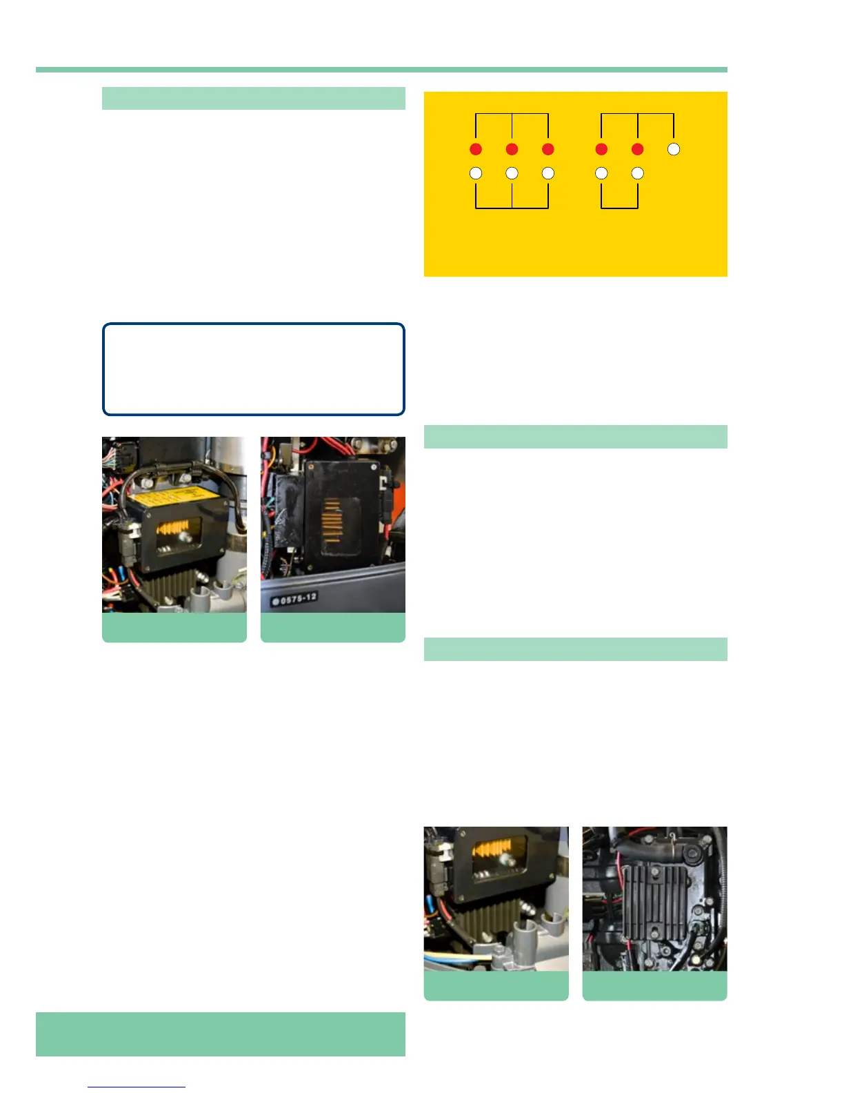
However if the fault remains then the particular circuit
affected needs to be investigated. On the top of the
Polyswitch box is a yellow tally that indicates which input/
output has a fault.
The tally reads from left to right:
• INPUT – positive feed from main engine supply.
• ENGINE/RELAY – positive feed to main engine relay.
• CHARGE – input from regulator to main supplies.
• TRIM/TILT – positive feed to trim/tilt motor.
• AIR VALVE – positive feed to airbox.
• CRANKING – illuminates on starting only.
Charging systems
The charging system uses the principles of magnetic
induction to produce electricity. Placing a permanent
magnet within a ring of conductors and rotating the
magnet induces a current in the conductor (coil). As the
North Pole is moved past a conductor coil, current will
be induced in one direction through the conductor. As
the South Pole moves past the conductor, the opposite
magnetic field causes current to be induced in the opposite
direction. Current is therefore induced in a back and forth
alternating flow in the conductor. This is called alternating
current (AC).
Regulator/rectifier
The lighting coil is located under the flywheel and produces
electricity for the charging circuit. The AC output from the
coil is fed to a regulator/rectifier.
The regulator/rectifier device rectifies the alternating
current into a direct current by using a series of diodes that
act as electrical one-way valves. The direct current (DC)
is required to charge the boat batteries. The amount of
current is regulated to ensure the batteries are charged to
the correct level and not over or under charged.
Polyswitches
A commercially available Yamaha F115 outboard engine
has a number of fuses fitted. The Inshore Lifeboat Centre
(ILC) have modified the RNLI engines in order to remove
the necessity of carrying spare fuses on the boat. This has
been done by fitting a box containing polyswitches.
Polyswitches are a form of self re-setting circuit breakers
and they are fully waterproof, obviously another advantage
should the boat capsize. Six circuits are protected in total
and they have a red LED connected to each output that
will illuminate if the polyswitch is operational. However
the ‘red on cranking’ LED only illuminates during the
cranking period.
NOTE
In the event of circuit failure with polyswitches you
simply turn off the power supply briefly and turn
it back on again, if the fault has cleared no further
action is required.
OK
INPUT
ENG RELAY
CHARGE
TRIM & TILT
AIR VALVE
RED ON CRANKING
FAULT
F115/OE 26
polyswitches
F115/OE 26
regulator/rectifier
F115A/OE 33
polyswitches
F115A/OE 33
regulator/rectifier