APR 2019 Chapter 25 Furnishings Page 25.21
25-73 Cargo Hook (continued)
F. Configurations for Flight (continued)
2. Configuration for Flight with Cargo Hook Installed
a. Remove (2) MS27039C0816 screws, (2) AN742-4 clamps, and (2) A130-
38 spacers securing D676-3 (control) cable assembly to F794-2 (access)
panel and belly; install (2) B526-6 (or MS27039C0806) screws. Verify
security.
b. Install hardware securing D136-3 bumpers and D136-2 support to G137-1
hardpoint installation rod ends. Standard torque fastener per § 20-32 and
torque stripe per Figure 5-1.
c. Remove FTC-4 cap (labeled “FC-4”) from hook harness assembly receptacle
on belly. Connect G140-6 (installations without load cell) or G140-7
(installations with load cell) harness assembly to receptacle; verify security.
Loop A215-149 o-ring around harness and control cable assembly. Install
ty-raps as required; cinch ty-raps until snug without over-tightening, and
trim tips flush with heads.
d. Install cargo hook per Part C steps 3 thru 10.
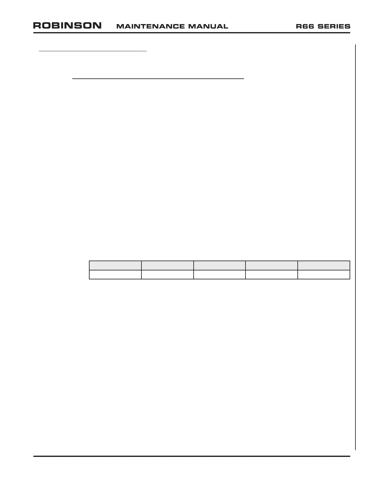
e. Revise Weight and Balance Record in R66 Pilot’s Operating Handbook (POH)
Section 6 to incorporate the following data:
Add:
Weight Long. Arm Long. Moment Lat. Arm Lat. Moment
3.90 lb 90.84 in. 354.28 in.-lb –4.10 in. –15.99 in.-lb