5-35 Telatemp Indicators
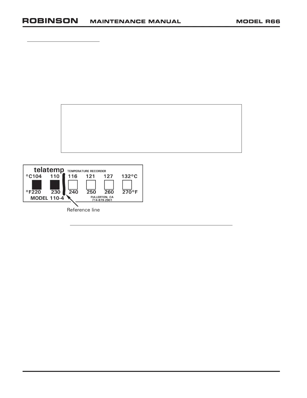
Refer to Figure 5-4. Self-adhesive Telatemp indicators record increases in operating
temperatures of the hydraulic pump and tail rotor gearbox. To use a Telatemp, draw a
reference line between the highest temperature square which has darkened during normal
operation and the next undarkened square. During every check thereafter, determine
if an additional square has blackened. If an indicated temperature increase cannot be
accounted for by a change in operating conditions, carefully examine the component
before further flight.
NOTE
Telatemps can indicate erroneously if contaminated by a
petroleum product, typically appearing as white, unactivated
square(s) between darkened squares at each end; replace any
Telatemp indicating as such and clean area with acetone prior
to installing.
Part Number Temperature Range
F110-2 60°C / 140°F — 88°C / 190°F
F110-3 82°C / 180°F — 110°C / 230°F
F110-4 104°C / 220°F — 132°C / 270°F
FIGURE 5-4 TELETEMP INDICATOR WITH DRAWN REFERENCE LINE
Page 5.6 Chapter 5 Inspections JUL 2020