Robustel R1520 User Guide
RT056_UG_R1520_v.1.0.3 Dec. 25, 2021 24/159
Connect the adapter or battery positive (red wire)
Connect the adapter or battery negative (black wire)
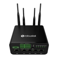
2.13 DI/DO Interface
R1520 supports 1 channel DI and 1 channel DO, the internal schematic diagram is as shown above;
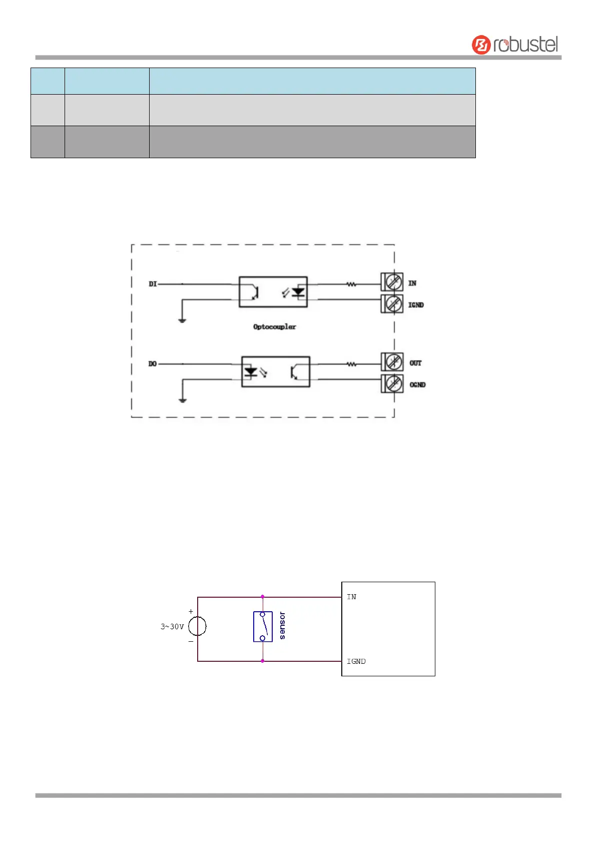
1. DI application
R1520 DI input is internally isolated by opt coupler, internal current-limiting design, within the working level of 0 ~
30V, external input does not need current limiting, DI input logic level range is as follows:
Logic 1 level range: min 3.5 V to max 30 V;
Logic 0 level range: min 0 V to max 1 V;
The application example is as follows:
2. DO application
R1520 DO output is internally isolated by opt ocoupler, OUT is OC gate output, Normal use requires external resistor
pull-up, the pull-up voltage range is 3V ~ 30V (for actual use, please consult Technical Support Engineer for selection
of pull-up resistor);
The application example is as follows: