32 Rockwell Automation Publication 2711P-UM008J-EN-P - April 2022
Chapter 2
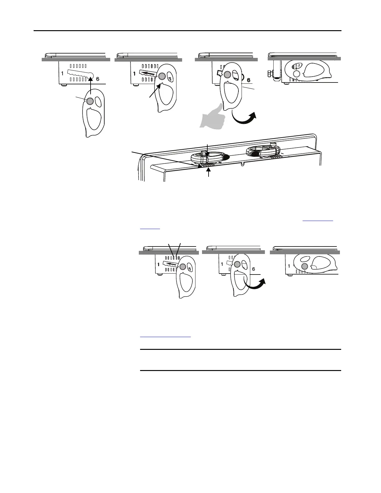
Initially, you secure the terminal in the panel by sliding each mounting lever to
a position that is one or two notches greater than the final lock position. For
example, if the final lock position is 3, slide each mounting lever to position 4
or 5. Follow the sequence specific to the terminal size shown in Figure 3 on
page 34.
You then adjust each lever to its final lock position in the same sequence. See
Figure 3 on page 34
.
This figure shows the lever orientation and lock sequence for a 10.4-in. touch
terminal.
Flat Side
Knob on reverse
side of lever
inserts into
large end of slot
1234
The edge of the bezel has alignment
indentations to assist with lever positioning.
The notch on the outside of the lever shows it
is locked in position 3.
You can use an erasable marker or grease pencil to mark the
indentations for visibility of slot positions.
Inner notch on lever
shows current lever
position.
TIP If the lock position is 6, slide lever to large end of slot or insertion hole.
IMPORTANT This process equalizes the pressure of the levers against the panel at a
gradual rate reducing the probability of broken clamps.
 Loading...


