Rockwell Automation Publication 2711P-UM008J-EN-P - April 2022 37
Chapter 2
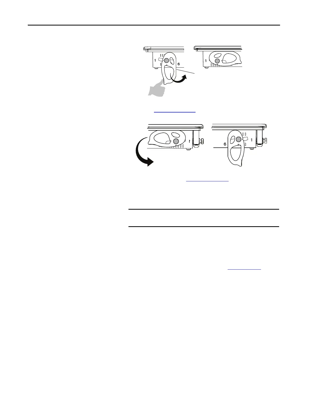
c. Rotate each lever until its flat side comes in contact with the panel.
5. Adjust each lever to its final lock position by using the same locking
sequence in Figure 3 on page 34
.
a. Unlock lever one in the sequence by rotating it away from the bezel.
b. With the lever positioned vertically to the slot, slide the lever to the
final locking position in Table 15 on page 31
.
The outer notch of the lever aligns with the bezel indentation.
c. Carefully rotate the lever back toward panel.
d. Lock the remaining levers to their final position.
IMPORTANT Do not use tools or excessive force to rotate the mounting levers.
The mounting levers are rotated and secured by hand.
TIP A broken mounting lever does not damage the terminal.
The mounting levers are designed to break off the pin if they are
over torqued. This breakage helps to prevent damage to the
terminal bezel. If a pin is broken, you can turn the lever around and
use the lever in another location. See Figure 3 on page 34
for details
and restrictions.
 Loading...


