Rockwell Automation Publication 440R-UM013G-EN-P - December 2022 13
Chapter 2
Installation
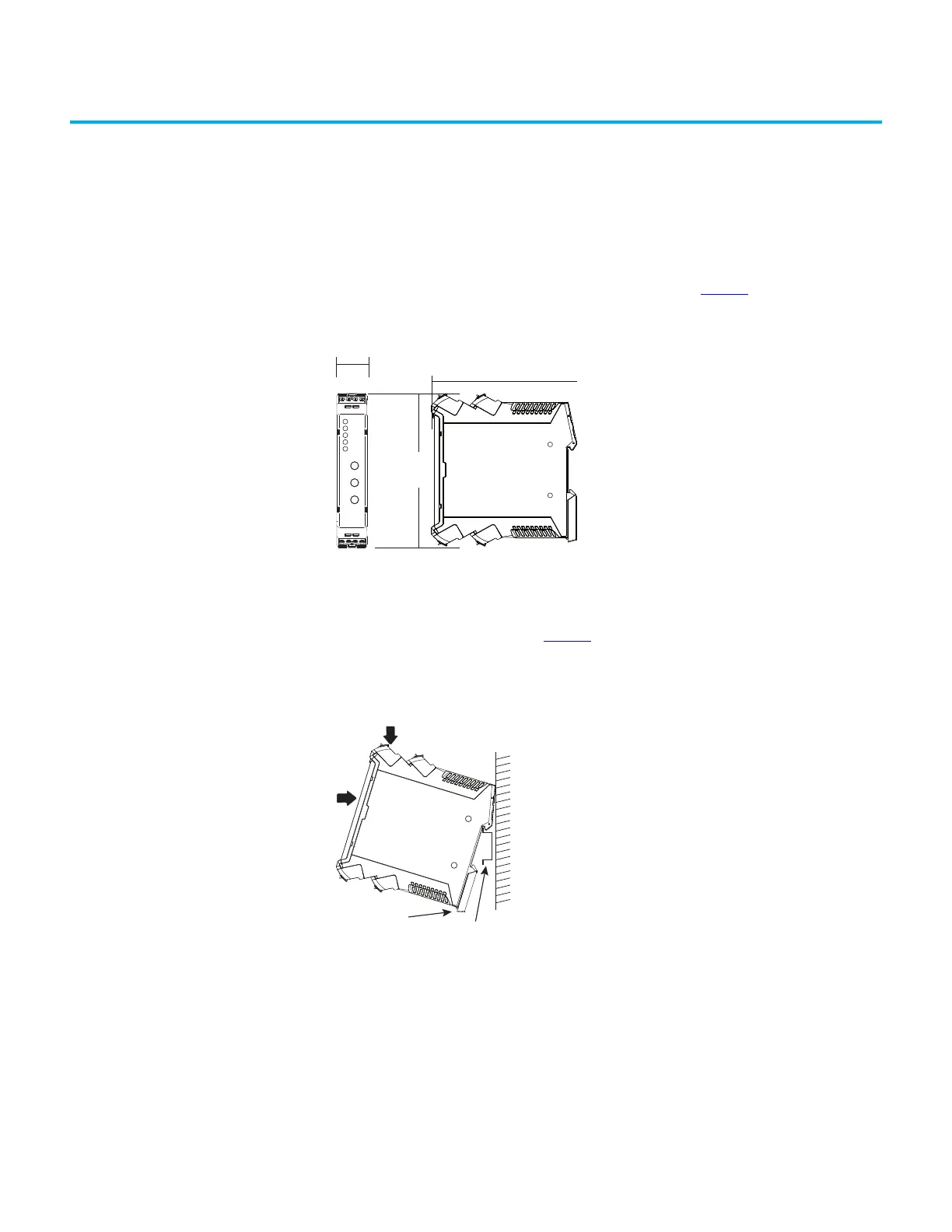
All safety relays in this manual have the same dimensions (see Figure 2).
Mounting Dimensions Figure 2 - Dimensions [mm (in.)]
DIN Rail Mounting and
Removal
Safety relays mount onto 35 mm (1.38 in.) DIN rails: 35 x 7.5 x 1 mm (1.38 x 0.3 x 0.04 in.)
(EN50022-35x7.5).
1. Hold the top at an angle (see Figure 3
).
2. Slide down until the housing catches the rail.
3. Swing the bottom down and push until the latch clips onto the rail.
Figure 3 - DIN Rail Mounting
Removal
To remove a safety relay, use a screwdriver to pry the DIN rail latch downwards until it is in the
unlatched position. Then, swing the module up.
113.6 (4.47)
119.14
(4.69)
22.5
(0.88)

 Loading...


